
User's Manual

Smart Machine Smart Decision
SIM5360A_User_Manual_V1.03 2014-07-03
24
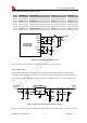
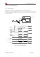
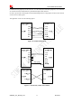
power will be preferable because of its better efficiency, especially at the high current situation. The
following figure is the reference circuit. Note that DCDC may deprave RF performance because of ripple
current intrinsically.
Figure 10: Reference circuit of the DCDC power supply
Volta ge monito r
To monitor the power supply voltage, user can use the AT command “AT+CBC”, this command has two
parameters: the battery status and the voltage value (mV). It will return the capacity percentage and actual
value of battery (at the VBAT pin). The voltage is continuously measured at intervals, whenever the
measured battery voltage is lower than a specific value set by the AT command “AT+CVALARM”. For
example, if the voltage value is set to be 3.4V, the following URC will be presented: “warning! voltage is
low: 3.3v”.
If the voltage is lower than a specific value which is set by the AT command “AT+CPMVT”, the module
will be powered off automatically and AT commands cannot be executed any more.
Note: Under-voltage warning function is disabled by default, user can enable it by the AT command
“AT+CVALARM”. Please refer to Document [1].
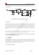
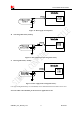
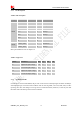
3.1.3 RTC Backup
The module uses RTC (Real Time Clock) to update and maintain inherent time and keeps system alive at
no power supply status. The RTC power supply of module can be provided by an external capacitor or a
battery (non-chargeable or rechargeable) through the VRTC. The following figures show various reference
circuits for RTC back up. The discharge current is less than 10uA.
External capacitor backup