
User's Manual

Smart Machine Smart Decision
SIM5360A_User_Manual_V1.03 2014-07-03
18
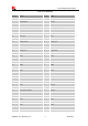
I2C interface
SCL 55 DO I2C clock output
None pulled up resistors in
the module. Pulled up with
a 2.2kR resistor to 1.8V
externally.
.
If it is unused, keep open.
SDA 56 I/O I2C data
Keypad interface
KBR0 29 DO
Bit 0 drive to the pad matrix
All Keypad pins can be
configured as GPIOs.
If it is unused, keep open.
KBR1 33 DO Bit 1 drive to the pad matrix
KBR2 30 DO Bit 2 drive to the pad matrix
KBR3 35 DO Bit 3 drive to the pad matrix
KBR4 34 DO Bit 4 drive to the pad matrix
KBC0 28 DI
Bit 0 for sensing key press on pad
matrix
KBC1 27 DI
Bit 1 for sensing key press on pad
matrix
KBC2 31 DI
Bit 2 for sensing key press on pad
matrix
KBC3 32 DI
Bit 3 for sensing key press on pad
matrix
KBC4 36 DI
Bit 4 for sensing key press on pad
matrix
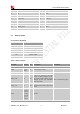
PCM interface
PCM_OUT/GPIO5 73 DO
PCM data output. It also can be
multiplexed as GPIO5.
If it is unused, keep open.
PCM_IN/GPIO0 74 DI
PCM data input. It also can be
multiplexed as GPIO0 with
module wake/interrupt.
PCM_SYNC/GPIO
2
75 DO
PCM data frame sync signal. It
also can be multiplexed as
GPIO2.
PCM_CLK/GPIO3 76 DO
PCM data bit clock. It also can be
multiplexed as GPIO3.
GPIOs
NETLIGHT/GPIO1 51 DO
Output PIN as LED control for
network status.
If it is unused, keep open.
GPIO4 54 DI
Input PIN as RF operating
control.
GPIO40 49 DO
Output PIN as operating status
indicating of module.
GPIO41 52 DO
General input/output PIN. It can
be used as wake/interrupt signal
to host from module
GPIO43 50 DI
General input/output PIN. It can
be used as wake/interrupt signal
to module from host.