
User's Guide

Smart Machine Smart Decision
SIM5360A EVB User Guide 03.18.2014
17
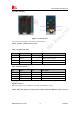
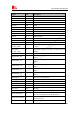
Table 10: IO interface
Signal I/O Description
GPIO40 I/O GPIO
POWER_ON I Power on the module
RESET I Reset the module
GPIO41 I/O GPIO
GPIO43 I/O GPIO
GPIO44 I/O GPIO
VDD_3V O 3V power supply
CURRENT_SINK I Current sink source
ADC1 I ADC
GPIO1 O Network status
GPIO4 I RF control switch
GPIO42
I/O GPIO
SPI_CS_N O SPI Chip selection
SPI_MISO
(UART_RXD)
I SPI Master input Slave output / Receive data of
UART2
SPI_MOSI
(UART_TXD)
O SPI Master output Slave input / Transmit data of
UART2
ADC2 I ADC
KEYSENSE_N0
I Bit 0 for sensing key press on pad
matrix
KEYSENSE_ N1
I Bit 1 for sensing key press on pad
matrix
KEYSENSE_ N2
I Bit 2 for sensing key press on pad
matrix
KEYSENSE_ N3
I Bit 3 for sensing key press on pad
matrix
KEYSENSE_ N4
I Bit 4 for sensing key press on pad
matrix
KEYPAD_0 O Bit 0 drive to the pad matrix
KEYPAD_1 O Bit 1 drive to the pad matrix
KEYPAD_2 O Bit 2 drive to the pad matrix
KEYPAD_3 O Bit 3 drive to the pad matrix
KEYPAD_4 O Bit 4 drive to the pad matrix
I2C_SDA I/O I2C data
I2C_SCL O I2C clock
PCM_DIN/GPIO0 I
General input pin for module wake up interrupt. It
also can be multiplexed as the PCM_DIN pin.
PCM_SYNC/GPIO2 I
General input pin. It also can be multiplexed as the
PCM_SYNC pin.
PCM_CLK/GPIO3 O General output pin. It also can be multiplexed as the