
User's Guide

Smart Machine Smart Decision
SIM5360A EVB User Guide 03.18.2014
10
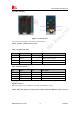
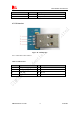
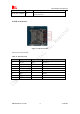
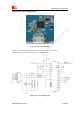
4.2 Audio Interface
Figure 4: Audio Interface
J306 is the handset interface. X501 is the headset interface.
NOTE: The MIC’s polarity must be correct.
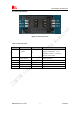
Table 3: Earphone interface
Pin Signal Input/Output Description
1 MIC1P I Positive microphone input
2 EAR_P O Positive receiver output
3 EAR_N O Negative receiver output
4 MIC1N I Negative microphone input
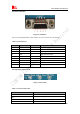
Table 4: Headset interface
Pin Signal I/O Description
5 GND Ground
6 HEADSET_MIC+ I Headset microphone input
7 HPH_L O Positive microphone output
8 HPH_R O Negative microphone output
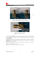
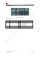
Speaker interface:
Please refer Figure 1. Pin 1 and Pin 2 is the SPK_M and SPK_P on J501.
NOTE: Audio cable must be away from the RF antenna, otherwise TDD noise may be occurred.