Development Kit Manual SIM5360A_EVB_User Guide_V1.
Document Title: SIM5360A EVB User Guide Version: 1.02 Date: 2014-03-18 Status: Release Document Control ID: SIM5360A_EVB_User Guide_V1.01 General Notes SIMCOM offers this information as a service to its customers, to support application and engineering efforts that use the products designed by SIMCOM. The information provided is based upon requirements specifically provided to SIMCOM by the customers.
Smart Machine Smart Decision Contents Contents ............................................................................................................................................ 2 Figure Index ...................................................................................................................................... 2 Table Index........................................................................................................................................ 3 Version History .....
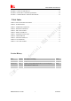
Smart Machine Smart Decision FIGURE 14: MICROUSB INTERFACE ............................................................................................... 19 FIGURE 15: UART TO USB CIRCUIT ................................................................................................ 19 FIGURE 16: EVB AND ACCESSORY EQUIPMENT ......................................................................... 20 FIGURE 17: USB INTERFACE UPDATE PROCEDURE ................................................................
Smart Machine Smart Decision 1 Overview This document gives the usage of SIM5360A EVB, user can get useful information about the SIM5360A EVB quickly through this document. The Debug board is designed for customer to design their own applications by using the 3G module SIM5360 easily. All the functions of the SIM5360A can be used by this board. One can use UART, USB interface to communicate with the SIM5360A. There is one UART interface, one USB 2.
Smart Machine Smart Decision 2 SIM5360A EVB SIM5360A EVB User Guide 5 03.18.
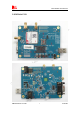
Smart Machine Smart Decision Figure 1: EVB view A: SIM5360A module B: Reset keypad C: Power on/off keypad D: IO interface 1(including GPIO, ADC, SPI, etc) E: LED indicator(including network status,operating status) F: Power supply selection jumper G: UART enable/disable switch(If user wants to use UART, please switch it to ON at first.
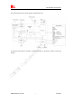
Smart Machine Smart Decision The following figure shows block diagram of SIM5360A EVB. All hardware Sub-interfaces included in SIM5360A EVB are described in detail in following chapters. SIM5360A EVB User Guide 7 03.18.
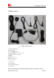
Smart Machine Smart Decision 3 EVB accessories Figure 2: EVB accessory A: USB to UART cable B: MAIN antenna Antenna Model: WT-C&G-28-90 Frequency Range (MHz) 824 ~ 960 1710 ~ 1990 VSWR ≤1.5 (900MHz) ≤2 (1800MHz) Gain: 1dBi Input Impedance (Ω): 50 Polarization Type: Vertical Connector Type: SMA C: USB cable D: 5V DC adapter E: GPS/GLONASS antenna F: DIV antenna NOTE: The maximum gain of the RF antenna gain should not exceed 1dBi for end-users. SIM5360A EVB User Guide 8 03.18.
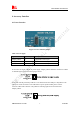
Smart Machine Smart Decision 4 Accessory Interface 4.1 Power Interface Figure 3: Power selection jumper Table 2: Power supply Signal Input/Output Description Adapter_VBAT O 3.8V/2A DC source input USB_VBAT O 3.8V/0.5A DC source input VBAT I SIM5360 DC source input If user wants to use DC adapter as power supply, Adapter_VBAT should be connected to VBAT on J202 through a jumper as following figure shows. This board could be powered by USB bus. User should connect the USB pin.
Smart Machine Smart Decision 4.2 Audio Interface Figure 4: Audio Interface J306 is the handset interface. X501 is the headset interface. NOTE: The MIC’s polarity must be correct.
Smart Machine Smart Decision 4.3 SIM card interface Figure 5: SIM card socket Table 5: SIM card socket Pin 1 Signal V_USIM Input/Output Description O USIM Card Power output automatic output on USIM mode,one is 3.0V±10%, another is 1.8V±10%. Current is about 10mA. 2 USIM_RESET O USIM Card Reset 3 USIM_CLK O USIM Card Clock 4 GND Ground 5 SIM_VPP Not connect 6 USIM_DATA SIM5360A EVB User Guide I/O USIM Card data I/O 11 03.18.
Smart Machine Smart Decision 4.4 Antenna Interface Figure 6: Main and diversity Antenna connector Figure 7:GPS Antenna connector SIMCom strongly recommends additional matching components between the antenna and the RF output of SIM5360 RF PAD (Main: pin 59; Diversity: PIN 82; GPS: pin 79;) for the application including an antenna. Topology is a PI structure plus a serial element; components assume to be capacitors or inductors depending on the antenna matching.
Smart Machine Smart Decision 4.5 RS232 Interface Figure 8: Serial Port J205 is 9 pins standard RS232 UART interface. It can be connected to a PC directly. Table 6: Serial Interface Pin Signal I/O Description 1 DCD O Data carrier detection 2 TXD O Transmit data 3 RXD I Receive data 4 DTR I Data Terminal Ready 5 GND Ground 6 NC NC 7 RTS I Request to Send 8 CTS O Clear to Send 9 RI O Ring Indicator 4.
Smart Machine Smart Decision LED I/O Description D201 O ADAPTER power indicator D202 O USB power indicator 4.7 USB interface Figure 10: USB Interface It is a normal 4Pin USB connector. Table 8: USB interface Pin Signal I/O Description 1 USB_VBUS I 5V 2 USB_DM I/O D+ line 3 USB_ DP I/O D- line 4 GND SIM5360A EVB User Guide Ground 14 03.18.
Smart Machine Smart Decision 4.8 Switch interface Figure 11: Switch Interface Table 9: Switch interface Switch Signal I/O Description 1 RS232 chip SHUTDOWN I UART switch 2 GPIO4 I RF switch (S301) ON : Normal mode OFF : Flight mode 3 RESET I Reset the module 4 PWRER_ON I Power on the module SIM5360A EVB User Guide 15 03.18.
Smart Machine Smart Decision 4.9 IO interface Figure 12: IO Interface SIM5360A EVB User Guide 16 03.18.
Smart Machine Smart Decision Table 10: IO interface Signal I/O Description GPIO40 I/O GPIO POWER_ON I Power on the module RESET I Reset the module GPIO41 I/O GPIO GPIO43 I/O GPIO GPIO44 I/O GPIO VDD_3V O 3V power supply CURRENT_SINK I Current sink source ADC1 I ADC GPIO1 O Network status GPIO4 GPIO42 I I/O RF control switch GPIO SPI_CS_N O SPI Chip selection SPI_MISO (UART_RXD) I SPI Master input Slave output / Receive data of UART2 SPI_MOSI (UART_TXD) O SPI Mast
Smart Machine Smart Decision PCM_CLK pin. PCM_DOUT/GPIO5 General output pin. It also can be multiplexed as the PCM_DOUT pin. O 4.10 SD card interface Figure 13: SD card socket J208 is the SD card interface.
Smart Machine Smart Decision 4.10 UART2 to MicroUSB interface Figure 14: MicroUSB interface J401 is 5 pins standard MicroUSB interface. It can be connected to a PC directly. The following figure is the uart to USB circuit of SIM5360-EVB. Figure 15: Uart to USB circuit SIM5360A EVB User Guide 19 03.18.
Smart Machine Smart Decision 5 EVB and accessory equipment At normal circumstance, the EVB and its accessories are equipped as the Figure below. Figure 16: EVB and accessory equipment 6 Quickly start 6.1 Running There are two ways to provide power supply to SIM5360 module: one is to use the 5V power supply provided in the EVB kit; the other is to use USB port of personal computer.
Smart Machine Smart Decision User can see the light on the EVB flashing at a certain frequency about 1.25Hz. By the state, user can judge whether the EVB and SIM5360 is running or not. No function and test can be executed if user has not connected necessary accessories. NOTE: This EVB board supports USB power supply when user connects USB_VBAT and VBAT together. 6.
Smart Machine Smart Decision (5) If user use UART to USB cable, user need to connect the cable to module serial port and the USB port of the computer, then follow step 1~3. 6.4 Downloading Connect the USB port line to the USB port, connect the direct current source adapter, run the download program, and choose the correct image, please follow the QDL downloading menu for the operation. Update procedure is described in the figure below. START Module power on Double click QDL.
Smart Machine Smart Decision Contact us: Shanghai SIMCom Wireless Solutions Ltd. Add: Building A,SIM Technology Building,No.633,Jinzhong Road,Changning Disdrict,Shanghai P.R. China 200335 Tel: +86-21-3252 3300 Fax: +86-21-3252 3301 URL: www.sim.com SIM5360A EVB User Guide 23 03.18.