
User Manual

Smart Machine Smart Decision
SIM7600A_User Manual_V1.01 2017-10-10
29
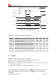
Table 12: USIM Electronic characteristic 3.0V mode (
USIM_VDD=2.95V)
Symbol Parameter
Min. Typ. Max. Unit
USIM_
VDD
LDO power output voltage
2.75 2.95 3.05 V
V
IH
High-level input voltage
0.65*USIM_VDD - USIM_VDD +0.3 V
V
IL
Low-level input voltage
-0.3 0 0.25*USIM_VDD V
V
OH
High-level output voltage
USIM_VDD -0.45 - USIM_VDD V
V
OL
Low-level output voltage
0 0 0.45 V
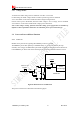
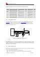
3.5.1 USIM Application Guide
It is recommended to use an ESD protection component such as ESDA6V1W5 produced by ST
(www.st.com
) or SMF15C produced by ON SEMI (www.onsemi.com ). Note that the USIM
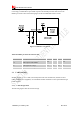
peripheral circuit should be close to the USIM card socket.The following figure shows the 6-pin
SIM card holder reference circuit.
Figure 18: USIM interface reference circuit
Note: USIM_DATA has been pulled up with a100KΩ resistor to USIM_VDD in module. A 100nF
capacitor on USIM_VDD is used to reduceinterference. For more details of AT commands about
USIM, please refer to document [1].
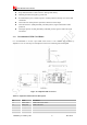
3.5.2 SIM Card Design Guide
SIM card signal could be interferenced by some high frequency signal, it is strongly recommended
to follow these guidelines while designing:
SIM card holder should be far away from antenna
SIM traces should keep away from RF lines, VBAT and high-speed signal lines