
User Manual

Smart Machine Smart Decision
SIM7600A_User Manual_V1.01 2017-10-10
17
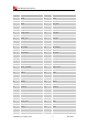
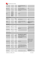
FLIGHTMODE
54 DI,PU
Flight Mode control input.
High level(or open): Normal
Mode
Low level: Flight Mode
DO NOT PULL UP
GPIO43 DURING
NORMAL POWER
UP!
STATUS 49 DO
Operating status output.
High level: Power on and
firmware ready
Low level: Power off
GPIO41 52 IO GPIO
GPIO43 50 IO GPIO
GPIO3 33 IO GPIO
GPIO6 34 IO GPIO
SD_DET 48 IO
Default: GPIO
Optional: SD card detecting
input.
H: SD card is removed
L: SD card is inserted
USIM_DET 53 IO
Default: GPIO
Optional: USIM card detecting
input.
H: USIM is removed
L: USIM is inserted
GPIO77 87 IO GPIO
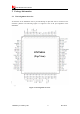
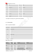
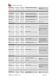
RF interface
MAIN _ANT 82 AIO MAIN antenna soldering pad
GNSS_ANT 79 AI GNSS antenna soldering pad
AUX_ANT 59 AI Auxiliary antenna soldering pad
Other interface
ISINK 45 PI Ground-referenced current sink.
If unused, please keep
them open.
ADC1 47 AI
Analog-digital converter input
1
ADC2 46 AI
Analog-digital converter input
2
COEX1 83 I/O
RF synchronizing between
Wi-Fi and LTE.
If unused, keep them
open.
DO NOT PULL UP
COEX1 AND COEX2
DURING NORMAL
POWER UP!
COEX2 84 I/O
COEX3 86 I/O
BOOT_CFG0 85 DI,PD
Boot configuration input.
Module will be forced into
USB download mode by
connect 85 pin to VDD_1V8
during power up.
Do place 2 test points
for debug.
DO NOT PULL UP
BOOT_CFG0
DURING NORMAL
POWER UP!
NC 42
No connection.
Keep it open