
User's Manual

Smart Machine Smart Decision
SIM7500A_User Manual_V1.00 2017-06-30
35
4 RF Specifications
4.1 LTE RF Specifications
Table 21: Conducted transmission power
Frequency Power Min.
LTE-FDD B4 23dBm +/-2.7dB <-40dBm
LTE-FDD B13 23dBm +/-2.7dB <-40dBm
Table 22: Operating frequencies
Frequency Receiving Transmission
LTE-FDD B4 2110~2155 MHz 1710 ~1755 MHz
LTE-FDD B13 777 ~787MHz 746~756 MHz
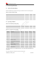
Table 23: Reference sensitivity (QPSK)
E-UTRA
band
3GPP standard Test value 3GPP standard
Duplex
1.4 MHz 3MHz 5MHz 10MHz 10 MHz 15 MHz 20 MHz
4 -104.7 -101.7 -100 -97 -102 -95.2 -94 FDD
13 -97 -94 -95 FDD
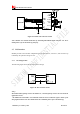
4.2 LTE Antenna Design Guide
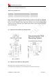
Users should connect antennas to Module’s antenna pads through the micro-strip line or other types
of RF trace. The trace impedance must be controlled in 50Ω. SIMCom recommends that the total
insertion loss between Module and antenna should meet the following requirements:
Table 24: Trace Loss
Frequency Loss
700MHz-960MHz <0.5dB
1710MHz-2170MHz <0.9dB
2300MHz-2650MHz <1.2dB
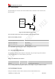
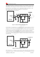
To facilitate the antenna tuning and certification test, a RF connector and an antenna matching
circuit should be added. The following figure is the recommended circuit.
SIM7500V provides LTE antenna named MAIN_ANT, customer could use 50Ω microstrip
line or stripline antenna connect to the module.