
User's Manual

SHANGHAI SIMCOM LIMITED
23
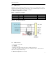
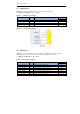
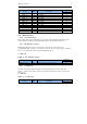
MIPI_CSI1_CLK_P 7 MIPI camera serial interface 1 clock – positive AI
MIPI_CSI1_CLK_N 8 MIPI camera serial interface 1 clock – negative AI
CAM_PWDN 121 Camera0 PWDN DO
CAM_I2C_SDA 63 Camera I2C,SDA B
CAM_I2C_SCL 64 Camera I2C,SCL DO
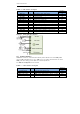
CAM1_RST_N 112 Camera 1 (rear camera) reset DO
CAM1_STANDBY_N 113 Camera 1 (rear camera) standby DO
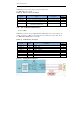
MIPI_CSI0_LN1_N 115 MIPI camera serial interface 0 clock – negative AI
,A
O
MIPI_CSI0_LN1_P 116 MIPI camera serial interface 0 clock – positive AI
,A
O
MIPI_CSI0_LN2_P 117 MIPI camera serial interface 0 lane 2 – positive AI
,A
O
MIPI_CSI0_LN2_N 118 MIPI camera serial interface 0 lane 2 – negative
AI
,A
O
MIPI_CSI0_CLK_N 119 MIPI camera serial interface 0 clock – negative AI
MIPI_CSI0_CLK_P 120 MIPI camera serial interface 0 clock – positive AI
CAM_MCLK0 122 Camera1 master clock 0 DO
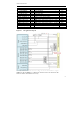
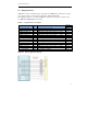
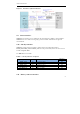
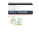
Figure4-3 CSI application diagram
Normally, camera need 2.85V and 1.8V voltage, we can use external LDO to replace
VREG_L6_1P8 and VERG_L17_2P85.At the same time, if the rear camera have AF
function, another external LDO is necessary.