
User's Manual

SHANGHAI SIMCOM LIMITED
20
4 Application Interface Specifications
_______________________________________________________________________________
4.1 Power interface
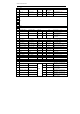
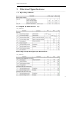
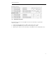
The power supply of SIMT1502 comes from PM8909. See Table4-1
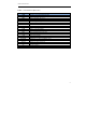
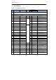
Table4-1 Power source description
Signal Pin#
Direction
Voltage(V) Current(mA)
PI/PO Min Typ Max Max
VREG_L11_2P95V 61 PO 1.75 2.95 3.337 600
VREG_L12_2P95V 85 PO 1.75 1.8/2.95
3.337 50
VREG_L17_2P85V 107 PO 1.75 2.85 3.337 420
VREG_L6_1P8V 109 PO 1.75 1.8 3.337 200
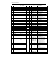
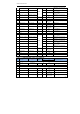
Signal Pin#
Direction
Functions
PI/PO
VBAT_SNS 88 PI Battery SNS
VBAT/VPH 92 PI/PO SYS Power
VBAT/VPH 124 PI/PO SYS Power
VBAT means battery, VPH means SYS Power. If you use the SIMT1502’s internal charging
management, they are the same function and they must be connected together. If you use external
charging management, PIN88 is Battery only and PIN92/124 is VPH only. You can see it in
SIMT1502_HW_compatibility design of the modification.pdf document.
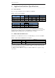
4.2 PMIC GPIO and MPP interface
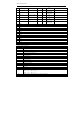
SIMT1502 have two PMIC GPIO interface and one PMIC Multipurpose interface.See Table4-2.
Table4-2 PMIC GPIO and MPP interface description
GPIO/MPP Pin#
Functions
PMU_GPIO01 81 RFCLK1_EN
PMU_GPIO02 83 RFCLK2_EN
PMU_MPP_2_PWM 79 PWM output
Two GPIOs are available. Some likely GPIO applications, which are described elsewhere: clock
outputs; external current driver control; external LDO, SMPS, or power gate controls; status bit;
XO controller input; and level translator.
One MPP are available. MPP can be configured as PWM, and MPP can be configured as analog
output buffers.