
User's Manual


Smart Machine Smart Decision
SIM868_Hardware_Design_V1.00 46 2016-06-20
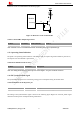
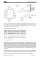
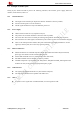
The RF test connector in the figure is used for the conducted RF performance test, and should be placed as close
as to the module’s antenna pin. The traces impedance between components must be controlled in 50Ω. The
component D101 is a bidirectional TVS component, which is used for ESD protection, the recommended part
numbers of the TVS are listed in the following table:
Table 31: Recommended TVS component
Package Type Supplier
0201 LXES03AAA1-098 Murata
0201 LXES03AAA1-154 Murata
0402 LXES15AAA1-153 Murata
0402 LXES15AAA1-100 Murata
0402 LXES15AAA1-017 Murata
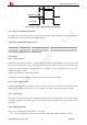
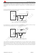
4.16.2. GNSS Antenna Interface
The module also provides a GNSS antenna interface named GPS_ANT to connect the antenna on the customer’s
application board. To obtain excellent GNSS reception performance, a good antenna will always be required.
Proper choice and placement of the antenna will ensure that satellites at all elevations can be seen, and therefore,
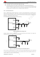
accurate fix measurements are obtained. There are two normal options: passive antenna and active antenna.
GNSS antenna choice should be based on the designing product and other conditions. For detailed Antenna
designing consideration, please refer to related antenna vendor’s design recommendation. The antenna vendor will
offer further technical support and tune their antenna characteristic to achieve successful GNSS reception
performance.
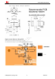
SIM868 provides GSM antenna named GSM_ANT, customer could use 50Ω microstrip line or stripline antenna
connect to the module. The maximum gain of the Main antenna gain should not exceed 3dBi considering the
SAR radio. No antenna gain may be used that would exceed the 2W EIRP power limit in 1900MHz band。