
User's Manual


Smart Machine Smart Decision
SIM868_Hardware_Design_V1.00 43 2016-06-20
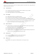
It is recommended that the GSM antenna should be placed as far as possible.
The isolations of the two antenna should be bigger than 30dB
The modular connection to the antenna is made through a host’s printed board microstrip trace
layout,the impendence of the microstrip trace is control in 50Ω,the series connection component in the
trace is 0Ω resistors for default, the size of series connection componentcan be 0402 or 0201.the length
of the microstrip trace should be as short as possible for reduce insertion loss.
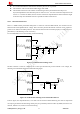
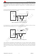
4.16.1. GSM Antenna Interface
There is a GSM antenna pad named GSM_ANT to connect an external GSM antenna, the connection of the
antenna must be decoupled from DC voltage. This is necessary because the antenna connector is DC coupled to
ground via an inductor for ESD protection. The external antenna must be matched properly to achieve the best
performance, so the matching circuit is necessary.
It is recommended to reserve the matching circuit as following:
Figure 37: GSM antenna matching circuit
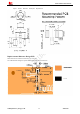
The RF connector is used for conduction test. If the space between RF pin and antenna is not enough, the
matching circuit should be designed as in the following figure:
Figure 38: GSM antenna matching circuit without RF connector
In above figure, the components R101, C101 and C102 are used for antenna matching, the value of components
can only be got after the antenna tuning, usually, they are provided by antenna vendor. By default, the R101 is 0Ω
resistors, and the C101, C102 are reserved for tuning.