
User's Manual


Smart Machine Smart Decision
SIM868_Hardware_Design_V1.00 42 2016-06-20
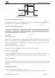
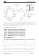
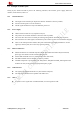
Transmit burst
RF_SYNC
577us
220us
Figure 36: RF_SYNC signal during transmit burst
4.14.1. RF_SYNC Multiplexing Function
RF_SYNC can also be used as GPIO to indicate the RF Jamming. The RF_SYNC function and RF Jamming
Detection function can be switched by AT+SJDR command.
Table 30: RF_SYNC Multiplexing function
Pin name Pin number Mode 0(default) Mode 1
RF_SYNC 29 RF Synchronization Signal
JD(RF jamming detection)
Note: About AT+SJDR, please refer to document [1].
4.15. GNSS
4.15.1. GNSS Overview
SIM868 provide a high-performance L1 GNSS solution for cellular handset applications. The solution offers
best-in-class acquisition and tracking sensitivity, Time-To-First-Fix (TTFF) and accuracy. The GNSS engine
supports both fully-autonomous operations for use in handheld consumer navigation devices and other
standalone navigation systems.
GNSS engine Performance, please refer to Table 3.
GNSS NMEA information is output by serial port. The default baud rate is 115200bps.
4.15.2. Power on/down GNSS
The GNSS engine is controlled by GNSS_EN PIN, so when it is necessary to run GNSS,the GNSS_EN must be
pulled up to 2.8V. When it is necessary to power off GNSS,the GNSS_EN must be pulled down to GND.
4.15.3. 1PPS Output
The 1PPS pin outputs pulse-per-second (1PPS) pulse signal for precise timing purposes. It will come out after
successfully positioning .The 1PPS signal can be provided through designated output pin for many external
applications.
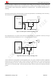
4.16. Antenna Interface
There are two antenna interfaces, GSM_ANT、GPS_ANT.
The input impendence of the two antenna should be 50Ω, and the VSWR should be less than 2.