
User's Manual
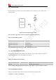
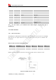
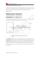
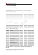
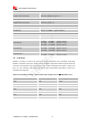
Table Of Contents
- Revision History
- Introduction
- Package Information
- Interface Application
- RF Specifications
- Electrical Specifications
- SMT Production Guide
- Packaging
- Appendix

Smart Machine Smart Decision
SIM7500A_User Manual_V1.022016-09-29
33
Note: The sinking current can be adjusted to meet the design requirement through the AT
command “AT+ CLEDITST =<0>, <value>”.The “value” ranges from 0 to 8, on behalf of the
current from 0mA to 40mA by 5mA step.
3.11.2 ADC
Module has 1 dedicated ADC pins named ADC. They are available fordigitizing analog signals
such as battery voltage and so on. These electronic specifications are shown in the following table.
Table 20: ADC Electronic Characteristics
Characteristics
Min.
Typ.
Max.
Unit
Resolution
–
15
–
Bits
Input Range
0.1
1.7
V
Input serial resistance
1
–
–
MΩ
Note: “AT+CADC” can be used to read the voltage of the ADC pins, for more details, please
refer to document [1].