
User's Manual
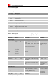
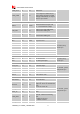
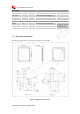
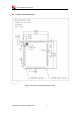
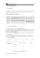
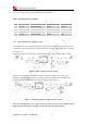
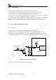
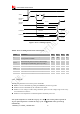
Table Of Contents
- Revision History
- Introduction
- Package Information
- Interface Application
- RF Specifications
- Electrical Specifications
- SMT Production Guide
- Packaging
- Appendix

Smart Machine Smart Decision
SIM7500A_User Manual_V1.022016-09-29
14
USIM_CLK
11
DO
USIM clock
USIM_VDD
14
PO
Power output for USIM card, its
output Voltage depends on USIM
card type automatically. Its output
current is up to 50Ma.
USB
VBUS
9
DI,PD
Valid USB detection input with
3.6~5.85V detection voltage
USB_DM
7
I/O
Negative line of the differential,
bi-directional USB signal.
USB_DP
8
I/O
Positiveline of the differential,
bi-directional USB signal.
UART interface
RTS
36
DOH
Request to send
If unused, keep
them open.
CTS
41
DI,PU
Clear to Send
RXD
39
DI,PU
Receive Data
RI
42
DOH
Ring Indicator
DCD
37
DOH
Carrier detects
TXD
38
DOH
Transmit Data
DTR
40
DI,PU
DTE get ready
I2C interface
SCL
4
DO
I2C clock output
If unused, keep
them open.
SDA
5
I/O
I2C data input/output
PCM interface
PCM_OUT
21
DO
PCM data output.
If unused, please
keep them open.
PCM_IN
20
DI
PCM data input.
PCM_SYNC
19
DO
PCM data frame sync signal.
PCM_CLK
18
DO
PCM data bit clock.
MCLK
17
DO
Audio Master clock
GPIO
NETLIGHT
52
DO
LED control output as network
status indication.
If unused, please
keep them open.
STATUS
50
DO
Operating status output.
High level: Power on and firmware
ready
Low level: Power off
GPIO_1
26
IO
GPIO
GPIO_49
49
IO
GPIO
USIM_DET
12
IO
Default: GPIO
Optional: USIM card detecting
input.
H: USIM is removed
L: USIM is inserted
GPIO_37
48
IO
GPIO