
User's Manual

Smart Machine Smart Decision
- 11 -
from DC voltage. This is necessary because the antenna connector is DC coupled to ground via an inductor for
ESD protection.
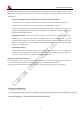
The external antenna must be matched properly to achieve best performance, so the matching circuit is
necessary, the connection is recommended as following:
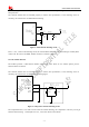
Figure1: GSM antenna matching circuit
R101,C101,C102 are the matching circuit, the value should be defined by the antenna design. normally R101
is 0Ω, C101 和 C102 are not SMD. The RF connector is used for conducted
5.2 GPS antenna interface
The module provides a GPS antenna interface named GPS_ANT. There are two normal options: passive
antenna and active antenna.
The external antenna must be matched properly to achieve best performance, so the matching circuit is
necessary, the connection is recommended as following figure:
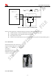
Figure 5: GPS passive antenna matching circuit
The components R101, C101 and C102 are used for antenna matching, the components’ value only can be got
after the antenna tuning. Normally R101 is 0Ω, C101 and C102 are not mounted.