
User's Manual

SIM800H Document
- 11 -
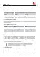
Figure1: GSM antenna matching circuit
R101ˈC101ˈC102 are the matching circuit, the value should be defined by the antenna design. normally R101
is 0, C101 ઼ C102 are not SMD. The RF connector is used for conducted
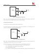
5.2 Bluetooth antenna interface
The module provides a Bluetooth antenna interface named BT_ANT.
The external antenna must be matched properly to achieve best performance, so the matching circuit is
necessary, the connection is recommended as following figure:
GND
Module
BT_ANT
GND
R201
C201
C202
BT
Antenna
Figure 5: BT antenna matching circuit
R201ˈC201ˈC202 are the matching circuit, the value should be defined by the antenna design. R201 is
recommended as 1.2NH and C202 is 1.5pF, C201 are not SMD.
There are some suggestions to components placing and lying for GSM and Bluetooth RF traces:
z The RF connector is used for conducted test, so keep it as close as pin RF_ANT;
z Antenna matching circuit should be closed to the antenna;
z Keep the RF traces as 50˗
z The RF traces should be kept far away from the high frequency signals and strong disturbing source.