
User Manual
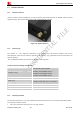
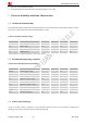
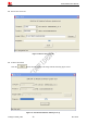
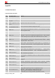
Table Of Contents

Smart Machine Smart Decision
Table 11: T5320 GPIOs
T5320 GPIO CPU Pin No. I/O Function
GPIO1 GPIO0
I/O
General input/output PIN. It can be used as wake/interrupt
signal to host from module If it is unused, left open.
GPIO2 GPIO2
I/O
General input/output PIN.
GPIO3 GPIO3
I/O
General input/output PIN.
GPIO4 GPIO5 I/O
General input/output PIN.
Example 1: If user use T5320 GPIO1 pin as an output GPIO:
1) AT+CGDRT=0,1 //set T5320 GPIO1 to output
2) AT+CGSETV=0,1 //set T5320 GPIO1 to high value
Example 2: If user use T5320 GPIO4 pin as an input GPIO:
1) AT+CGDRT=5,0 //set T5320 GPIO4 to input
Please refer to document [1] and document [2] for details.
6.4 LED indicator
A red led indicates the power status, when a valid power appears, the red led will lighten up. But a lighten up red
led does not mean that the terminal has been powered up.
A green led indicates the terminal status and GSM net status, after the terminal been powered up and registered to
the network, it will blink at a certain frequency.
Figure 15: Indicator LED
Table 12: Status of the NETLIGHT indicator (Green)
LED Status T5320 behavior
Always On Searching Network/Call Connect
200ms ON, 200ms OFF Data Transmit
800ms ON, 800ms OFF Registered network
Off
Power off / Sleep
T5320_User Guide_V1.04 21 2013- 04-15