
User's Manual
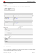
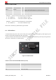
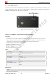
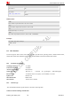
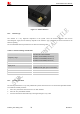
Table Of Contents
- Contents
- Version History
- 1 Introduction
- 2 Key features
- 3 Terminal dimensions
- 4 Installation
- 5 Interface introduction
- 6 Application Interface
- 7 Electrical, Reliability and Radio Characteristics
- 8 Software/ Firmware Upgrade
- Appendix

Smart Machine Smart Decision
T5320+G_User Guide_V1.01 27 2013-04-15
Patch
Center Frequency 1575.42MHz
Bandwidth(10db return loss) 10MHZ min.
Polarization R.H.C.P
LNA(for Active antenna)
Center Frequency 1575.42MHz
VSWR ≤2.0
Gain 27db typ.
Voltage DC 3.3*0.6 V
6.8.3 GPS operating
The DC3V voltage for active antenna is controlled by GPIO43.
Passive antenna
If user use passive antenna, The DC3V voltage must be cut off by GPIO43.
1) AT+CGFUNC=12,0 //set T5320+G GPIO43 to general GPIO
2) AT+CGDRT=43,1 //set T5320+G GPIO43 to output
3) AT+CGSETV=43,0 //set T5320+G GPIO43 to low value
4) AT+CGPS=1,1 // start GPS, standalone mode
Active antenna
If user use active antenna, The DC3V voltage must be exist for active antenna.
1) AT+CGFUNC=12,0 //set T5320+G GPIO43 to general GPIO
2) AT+CGDRT=43,1 //set T5320+G GPIO43 to output
3) AT+CGSETV=43,1 //set T5320+G GPIO43 to high value
4) AT+CGPS=1,1 // start GPS, standalone mode
Please refer to document [1] and document [23] for details.
6.9 Antenna interface
6.9.1 Antenna connector
Antenna connector allows transmission of radio frequency (RF) signals between the modem and the external
supplied antenna. The T5320+G modem is fitted with a 50Ω male SMA connector.