
User's Manual
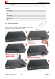
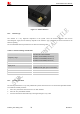
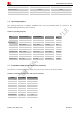
Table Of Contents
- Contents
- Version History
- 1 Introduction
- 2 Key features
- 3 Terminal dimensions
- 4 Installation
- 5 Interface introduction
- 6 Application Interface
- 7 Electrical, Reliability and Radio Characteristics
- 8 Software/ Firmware Upgrade
- Appendix

Smart Machine Smart Decision
T5320+G_User Guide_V1.01 25 2013-04-15
Figure 16: Installation of SIM Card
6.7 I2C Interface
T5320+G provides a I2C interface. I2C is used to communicate with peripheral equipments and can be operated
as either a transmitter or receiver, depending on the device function. Use AT Commands “AT+CRIIC and
AT+CWIIC” to read/write register values of related peripheral equipments connected with I2C interface.
Table 14: AT+CRIIC Read values from register of IIC device
Description
Read values from register of IIC device.
SIM PIN References
NO Vendor
Syntax
Test Command Responses
AT+CRIIC=? OK
Write Command Responses
+CRIIC: <data>
OK
AT+CRIIC=
<addr>,<reg>,<len>
ERROR
Defined values
<addr>
Device address. Input format must be hex, such as 0xFF.
<reg>
Register address. Input format must be hex, such as 0xFF.
<len>
Read length. Range:1-4; unit:byte.
<data>
Data read. Input format must be hex, such as 0xFF – 0xFFFFFFFF.
Examples
AT+CRIIC=0x0F, 0x0F, 2
+CRIIC: FFFF
OK
Table 15: AT+CWIIC Write values to register of IIC device
Description
Write values to register of IIC device.
SIM PIN References
NO Vendor
Syntax