
User's Manual
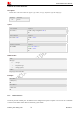
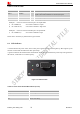
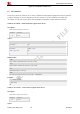
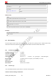
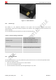
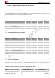
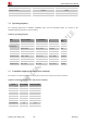
Table Of Contents
- Contents
- Version History
- 1 Introduction
- 2 Key features
- 3 Terminal dimensions
- 4 Installation
- 5 Interface introduction
- 6 Application Interface
- 7 Electrical, Reliability and Radio Characteristics
- 8 Software/ Firmware Upgrade
- Appendix

Smart Machine Smart Decision
T5320+G_User Guide_V1.01 21 2013-04-15
Table 10: AT+CADC Read ADC
Description
Read the ADC value from modem. We support 3 type of ADC, raw type, temperature type and voltage type.
SIM PIN References
NO Vendor
Syntax
Test Command Responses
AT+CADC=? +CADC: (range of supported <adc>s)
OK
Write Command Responses
+CADC: <value>
OK
AT+CADC=<adc>
ERROR
Execution Command Responses
AT+CADC
Same as AT+CADC= 0:
+CADC: <value>
OK
Defined values
<adc>
ADC type:
0 – raw type.
1 – temperature type.
2 – voltage type(mv)
<value>
Integer type value of the ADC.
Examples
AT+CADC=?
+CADC:(0-2)
OK
AT+CADC=0
+CADC: 187
OK
6.3.3 GPIO interfaces
T5320+G provides 3 GPIO pins. All GPIOs can be configured as inputs or outputs. User can use AT Commands
to read or write GPIOs status. Refer to document [1] for details.