
User's Manual
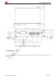
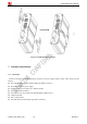
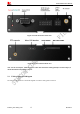
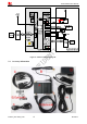
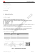
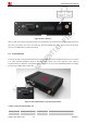
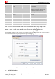
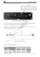
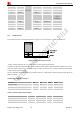
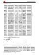
Table Of Contents
- Contents
- Version History
- 1 Introduction
- 2 Key features
- 3 Terminal dimensions
- 4 Installation
- 5 Interface introduction
- 6 Application Interface
- 7 Electrical, Reliability and Radio Characteristics
- 8 Software/ Firmware Upgrade
- Appendix

Smart Machine Smart Decision
T5320+G_User Guide_V1.01 20 2013-04-15
Table 8: Audio parameter
Parameter Influence to Range Gain range Calculation AT command
micAmp1
MICP/MICN
analogue amplifier
gain before ADC
0…1 0…24dB 2 steps AT+CMICAMP1
txVol
Digital gain of input
signal after ADC
0,
1...65535
Mute,
-84...+12dB
20 * log
(txVol/
16384)
AT+CTXVOL
txGain
Digital gain of input
signal after
summation of
sidetone
0,
1...65535
Mute,
-84...+12dB
20 * log
(txGain/
16384)
AT+CTXGAIN
txFilter
Input PCM 13-tap
filter parameters, 7
values
0...65535 ---
MATLAB
calculate
AT+CTXFTR
rxGain
Digital gain of
output signal after
summation of
sidetone
0,
1...65535
Mute,
-84...+12dB
20 * log
(rxGain/
16384)
AT+CRXGAIN
rxVol
Digital Volume of
output signal after
speech decoder,
before summation of
sidetone and DAC
-300…300 dbm
-300…300d
bm
AT+CLVL
AT+CVLVL
AT+CRXVOL
stGain
Digital attenuation
of sidetone
0, 1...65535
Mute,
-96...0dB
20 * log
(stGain/
16384) -12
AT+SIDET
rxFilter
Output PCM 13-tap
filter parameters, 7
values
0...65535 ---
MATLAB
calculate
AT+CRXFTR
Please refer to document [1] and document [3] for details.
6.3.2 ADC channel
T5320+G provides an auxiliary ADC, which can be used to measure the voltage. User can use AT command
“AT+CADC=2” to read the voltage value.
Table 9: ADC specification
Parameter Min Typ Max Unit
Voltage range 0 - 2.2 V
ADC Resolution - 12 - Bits
Sampling rate - - 200K Hz
Note: the maximum voltage that the ADC can gather is 2.2V