
User's Manual
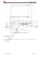
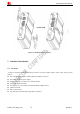
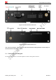
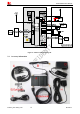
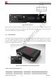
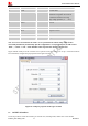
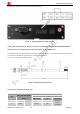
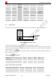
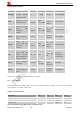
Table Of Contents
- Contents
- Version History
- 1 Introduction
- 2 Key features
- 3 Terminal dimensions
- 4 Installation
- 5 Interface introduction
- 6 Application Interface
- 7 Electrical, Reliability and Radio Characteristics
- 8 Software/ Firmware Upgrade
- Appendix

Smart Machine Smart Decision
3 Black GND Ground
4 Orange SPK+ O
5 Brown MIC+ I
6 White I2C_SCL I/O Configurable
by AT
commands
7 Gray V_4V DC OUT
8 Red ADC I
9 Purple SPK- O
10 Blue
1007 26#
MIC- I
6.3.1 Audio interface
T5320+G has one pair of audio input and audio output; it can be connected to a speakerphone directly.
Figure 13: Speaker reference circuit
Firstly, customer must use the “AT +CSDVC=3” to select speaker audio channel.
Customer can set the terminal MIC gain level to make the sounds louder so that the listener can hear more clearly.
And if the sound a little lower on the terminal side, customer can use the “AT +CLVL” to make the sound higher
so that customer can hear clearly.
The AT commands should be send to the terminal by RS232 or USB interface, and the following table shows the
detail commands.
Table 6: MIC input characteristics
Parameter Min Typ Max Unit
Working Voltage - 1.8 - V
Working Current 0.07 0.4 1 mA
External Microphone Load Resistance 1.2 2.2 k Ohms
Table 7: Speaker output characteristics
Parameter Min Typ Max Unit
Quiescent Current - 2.5 4 mA
Load resistance - 8 - Ohm
Output power(1KHz) - 500 - mW
T5320+G_User Guide_V1.01 19 2013-04-15