
User's Manual

SIM900L Document
- 9 -
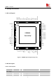
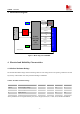
3. Detail Block Diagram
Figure 5: Block diagram of SIM900L
4. Electrical and Reliability Characteristics
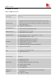
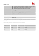
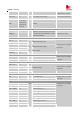
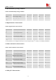
4.1 Absolute Maximum Ratings
The absolute maximum ratings stated in following table are stress ratings under non-operating conditions. Stresses
beyond any of these limits will cause permanent damage to SIM900L.
Table 4: Absolute maximum ratings
Symbol Parameter Min Typ Max Unit
VBAT Power supply voltage - - 5.5 V
V
I
*
Input voltage -0.3 - 3.1 V
I
I
*
Input current - - 10 mA
I
O
*
Output current - - 10 mA
*
These parameters are for digital interface pins, such as keypad, GPIO, I
2
C, UART, LCD, PWMs and DEBUG.
26M
32
K
FLASH
Application Interface (68PIN,SMT TYPE)
A
[
0:21
]
D
[
0:16
]
UART
DBG
VBACKUP
GPIO
SPI
AUDIO
VEXT
KEYPAD
PWRKEY
PAM(PA+SW ITCH)
RF7161
PNX4851
Intergrading
DBB,ABB
and
Transceiver
SAW
Filter
Antenna PAD