
User's Manual
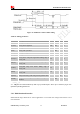
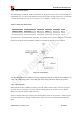
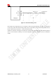
Table Of Contents
- RevisionHistory
- Introduction
- PackageInformation
- ApplicationInterfaceSpecification
- RFSpecification
- ReliabilityandOperatingCharacteristics
- GuideforProduction
- Appendix

Smart Machine Smart Decision
SIM5320ALD_User Manual_V1.01 2014-08-20
49
Figure 39: Antenna matching circuit
In this figure, the components R1,C1,C2 and R2 is used for antenna matching, the value of components
can only be got after the antenna tuning, usually, they are provided by antenna vendor. By default, the R1,
R2 are 0 ohm resistors, and the C1, C2 are reserved for tuning.
The RF test connector in the figure is used for the conducted RF performance test, and should be placed as
close as to the module’s antenna pin. The traces impedance between components must be controlled in
50ohm.