
User's Manual
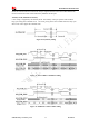
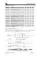
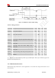
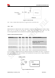
Table Of Contents
- RevisionHistory
- Introduction
- PackageInformation
- ApplicationInterfaceSpecification
- RFSpecification
- ReliabilityandOperatingCharacteristics
- GuideforProduction
- Appendix

Smart Machine Smart Decision
SIM5320ALD_User Manual_V1.01 2014-08-20
41
Table 26: Control status
GPIO4 Status Module operation
Low Level Flight Mode: RF is closed.
High Level Normal Mode: RF is working.
Note
:
1. When the module is powered off, make sure all digital interfaces (UART, etc) connected with peripheral devices have
no voltage higher than 0.3V. If users’ design cannot meet above conditions, high level voltages maybe occur in GPIO
pins because current leakage from above digital interfaces may occur.
3.9.3 Pin Description
Table 27: Electronic characteristic
Pin name
DC Characteristics
Min Typ Max
PCM_CLK -0.3 2.6 2.9
PCM_SYNC -0.3 2.6 2.9
PCM_DOUT -0.3 2.6 2.9
PCM_DIN -0.3 2.6 2.9
Table 28: Pin description
Pins Pin No.
AUX_PCM
functionality
Primary PCM
functionality
Description
PCM_DIN/GPIO0 74 AUX_PCM_DIN PCM_DIN PCM data input
PCM_SYNC/GPIO2 75 AUX_PCM_SYNC PCM_SYNC PCM data synchrony
PCM_DOUT/GPIO5 73 AUX_PCM_DOUT PCM_DOUT PCM data output
PCM_CLK/GPIO3 76 AUX_PCM_CLK PCM_CLK PCM data clock
3.9.4 Signal Description
The default PCM interface in SIM5320 is the auxiliary PCM interface. The data changes on the high level
of PCM_CLK and is sampled at the falling edge of PCM_CLK in one period. Primary PCM is disabled
after every power-on or every reset event. So user must use AT command to enable the primary PCM
mode after powering on or resetting the module every time if user wants to use Primary PCM.SIM5320
PCM Interface can be operated in Master or Slave mode if it is configured to primary PCM. In Master
Mode, the Module drives the clock and sync signals that are sent to the external codec. When it is in Slave