
User's Manual
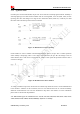
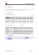
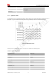
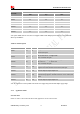
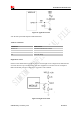
Table Of Contents
- RevisionHistory
- Introduction
- PackageInformation
- ApplicationInterfaceSpecification
- RFSpecification
- ReliabilityandOperatingCharacteristics
- GuideforProduction
- Appendix

Smart Machine Smart Decision
SIM5320ALD_User Manual_V1.01 2014-08-20
36
KEYPAD_0 30
Driving pads
KEYPAD_1 29
KEYPAD_2 30
KEYPAD_3 35
KEYPAD_4 34
3.6.2 Application Guide
All keypad pins can be configured for GPIOs. These GPIOs also support interruption operation if used as
input pins. A typical circuit about the keypad (5*5 keypad matrix) is shown in the following figure.
Figure 26: Reference circuit
If these pins are configured for GPIOs, the sequence is listed in the following table.
Table 19: GPIO configuration
Keypad interface GPIO No.
KEYPAD_4 GPIO6
KEYPAD_3 GPIO7
KEYPAD_2 GPIO8
KEYPAD_1 GPIO9
KEYPAD_0 GPIO10
KEYSENSE_N4 GPIO11
KEYSENSE_N 3 GPIO12
KEYSENSE_N 2 GPIO13
KEYSENSE_N 1 GPIO14