
User's Guide
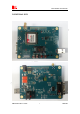
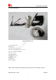
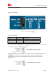
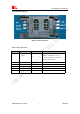
Table Of Contents

Smart Machine Smart Decision
SIM5320AL EVB User Guide 20.08.2014
2
Contents
Contents...............................................................................................................................................2
Figure Index........................................................................................................................................ 2
Table Index........................................................................................................................................3
Version History................................................................................................................................... 3
1 Overview.......................................................................................................................................... 4
2 SIM5320AL EVB............................................................................................................................ 5
3 EVB accessories...............................................................................................................................7
4 Accessory Interface..........................................................................................................................8
4.1 Power Interface.......................................................................................................................8
4.2 SIM card interface.................................................................................................................. 9
4.3 Antenna Interface................................................................................................................. 10
4.4 RS232 Interface....................................................................................................................10
4.5 Operating Status LED.......................................................................................................... 11
4.6 USB interface....................................................................................................................... 12
4.7 Switch interface....................................................................................................................13
4.8 IO interface...........................................................................................................................14
5 Quickly start................................................................................................................................... 16
5.1 Running................................................................................................................................ 16
5.2 Installing Driver................................................................................................................... 16
5.3 Connecting Net and calling..................................................................................................17
5.4 Downloading........................................................................................................................ 17
5.5 Turning off............................................................................................................................18
6.6 Measuring the current consumption.....................................................................................18
Figure Index
FIGURE 1: EVB VIEW............................................................................................................................ 6
FIGURE 2: EVB ACCESSORY............................................................................................................... 7
FIGURE 3: POWER SELECTION JUMPER...........................................................................................8
FIGURE 5: SIM CARD SOCKET............................................................................................................ 9
FIGURE 6: MAIN ANTENNA CONNECTOR...................................................................................... 10
FIGURE 8: SERIAL PORT.....................................................................................................................10
FIGURE 9: STATUS LED.......................................................................................................................11
FIGURE 10: USB INTERFACE............................................................................................................. 12
FIGURE 11: SWITCH INTERFACE...................................................................................................... 13
FIGURE 12: IO INTERFACE................................................................................................................. 14
FIGURE 14: USB INTERFACE UPDATE PROCEDURE....................................................................18
FIGURE 15: CURRENT CONSUMPTION IN THE SLEEP MODE.................................................... 19