
User's Manual

Smart Machine Smart Decision
SIM5320AD EVB User Guide 02.04.2011
6
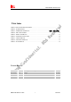
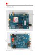
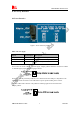
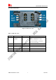
Figure 1: EVB view
A: SIM5320AD module
B: Reset keypad
C: Power on/off keypad
D: IO interface 1(including GPIO, ADC, SPI, etc)
E: LED indicator(including network status,operating status)
F: Power supply selection jumper
G: UART enable/disable switch
H: RF enable/disable (flight mode) switch
I: USB connector
J: SIM card socket
K:
IO interface 2(including PCM,GPIO, UART, I2C, etc)
L: GPS antenna SMA
M: Main antenna SMA
O: UART connector
P: Adapter connector
Q: SIM5320AD JTAG test point
T: Speaker interface
All hardware Sub-interfaces included in SIM5320AD EVB are described in detail in following
chapters.