
User's Manual
Smart Machine Smart Decision
SIM5320A_Hardware Design_V1.01 2011-2-29
53
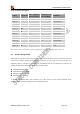
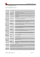
Table 32: Electronic characteristic
Symbol Description Min Typ Max Unit
CURRENT_SINK Input voltage 0.5 VDD 5 V
I
O
Input current - - 150 mA
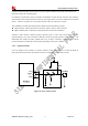
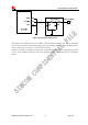
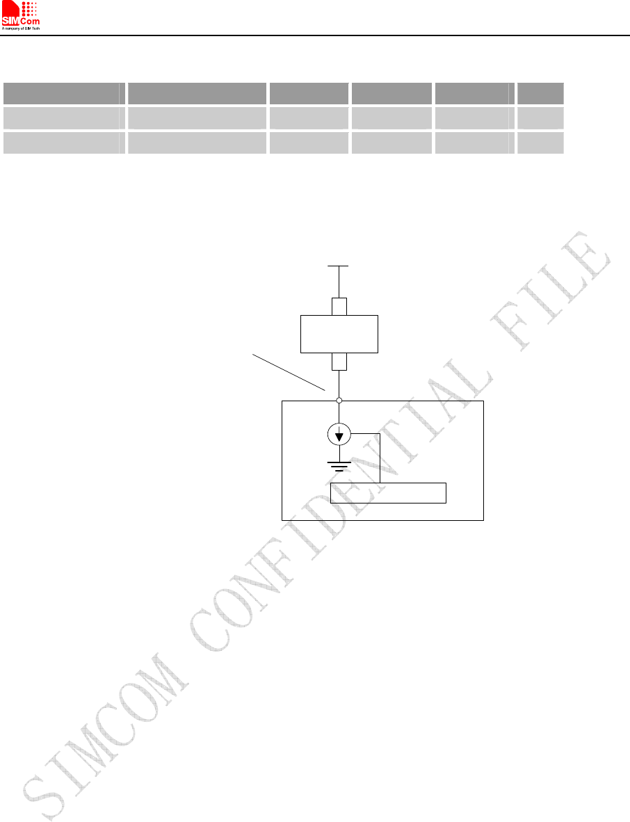
Since the driver is ground-referenced current sink, the operating device it drives must form a current path
between the VDD pin and the CURRENT_SINK pin. The following figure is for users reference.
MODULE
CURRENT_SINK
Pin 45 is +5V tolerant-
suitable for driving white
LEDs
Current Controls
Passive
device
+
-
VBAT
High
current
Figure 41: Current drive
Note: The sinking current can be adjusted to meet design requirement through the AT command “AT+ CLEDITST =<0>,
<value>”.The “value” ranges from 0 to 15,on behalf of the current changes from 0mA to 150mA in steps of 10mA.
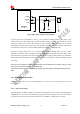
3.13.2 Reset Function
SIM5320A also have a RESET pin (PIN4) to reset the module. This function is used as an emergency reset
only when AT command “AT+CPOF” and the POWER_ON pin has no effect. User can pull the RESET
pin to ground, then the module will reset.
This pin is already pulled up in module, so the external pull-up resistor is not necessary. A 100nF capacitor
close to the RESET pin is strongly recommended. A reference circuit is recommended in the following
figure.