
User's Manual
Smart Machine Smart Decision
SIM5320A_Hardware Design_V1.01 2011-2-29
46
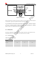
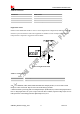
3.11 PCM Interface
SIM5320A provides hardware PCM interface for external codec. The PCM interface enables
communication with an external codec to support hands-free applications. SIM5320A PCM interface can
be used in two modes: the default mode is auxiliary PCM (8 KHz long sync mode at 128 KHz PCM CLK);
the other mode is primary PCM (8 KHz short sync mode at 2048 KHz PCM CLK). In short-sync
(primary PCM) mode, SIM5320A can be a master or a slave. In long-sync (auxiliary PCM) mode,
SIM5320A is always a master. SIM5320A also supports 3 kinds of coding formats: 8 bits (
υ-law or A-law)
and 16 bits (linear).
Note: PCM interface is multiplexed from GPIO (default setting). The AT command “AT+CPCM” is used to switch
between PCM and GPIO functions. Please refer to document [22] and document [1] for details.
3.11.1 Pin Description
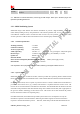
Table 28: Electronic characteristic
2.6V mode
Pin name
Min Typ Max
PCM_CLK 2.5 2.6 2.7
PCM_SYNC 2.5 2.6 2.7
PCM_DOUT 2.5 2.6 2.7
PCM_DIN 2.5 2.6 2.7
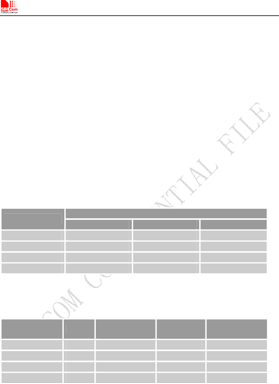
Table 29: Pin description
Pins Pin No.
AUX_PCM
functionality
Primary PCM
functionality
Description
PCM_DIN/GPIO0 74 AUX_PCM_DIN PCM_DIN PCM data input
PCM_SYNC/GPIO2 75 AUX_PCM_SYNC PCM_SYNC PCM data synchrony
PCM_DOUT/GPIO5 73 AUX_PCM_DOUT PCM_DOUT PCM data output
PCM_CLK/GPIO3 76 AUX_PCM_CLK PCM_CLK PCM data clock
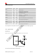
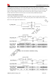
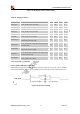
3.11.2 Signal Description
The default PCM interface in SIM5320A is the auxiliary PCM interface. The data changes on the high
level of PCM_CLK and is sampled at the falling edge of PCM_CLK in one period. Primary PCM is
disabled after every power-on or every reset event. So user must use AT command to enable the primary