
User's Manual
Smart Machine Smart Decision
SIM5320A_Hardware Design_V1.01 2011-2-29
45
Table 26: LED status
LED Status Module Status
Always On Searching Network/Call Connect
200ms ON, 200ms OFF Data Transmit
800ms ON, 800ms OFF Registered network
Off
Power off / Sleep
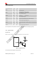
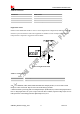
Flight mode control
GPIO4 controls SIM5320A module to enter or exit the Flight mode. In Flight mode, SIM5320A closes RF
function to prevent interference with other equipments or minimize current consumption. Bidirectional
ESD protection component is suggested to add on GPIO4.
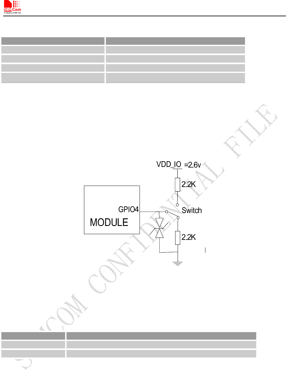
Figure 32: Flight mode switch
Table 27: Control status
GPIO4 Status Module operation
Low Level Flight Mode: RF is closed.
High Level Normal Mode: RF is working.
Note
:
1. For SIM5320A, GPIO0, GPIO2, GPIO3 and GPIO5 have multiplex function, user can use them as PCM
interface to connect extend codec. Refer to section 3.10 and document [1] for details.
2. When the module is powered off, make sure all digital interfaces (PCM UART, etc) connected with peripheral devices
have no voltage higher than 0.3V. If users’ design cannot meet above conditions, high level voltages maybe occur in
GPIO pins because current leakage from above digital interfaces may occur.