
User's Manual

Smart Machine Smart Decision
SIM5320A_Hardware Design_V1.01 2011-2-29
36
and mechanical design.
3.5 USIM Interface
The USIM provides the required subscription verification information to allow the mobile equipment to
attach to a GSM or UMTS network. Both 1.8V and 3.0V SIM Cards are supported.
3.5.1 Pin description
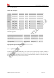
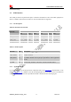
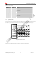
Table 16: Electronic characteristic
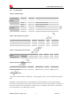
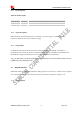
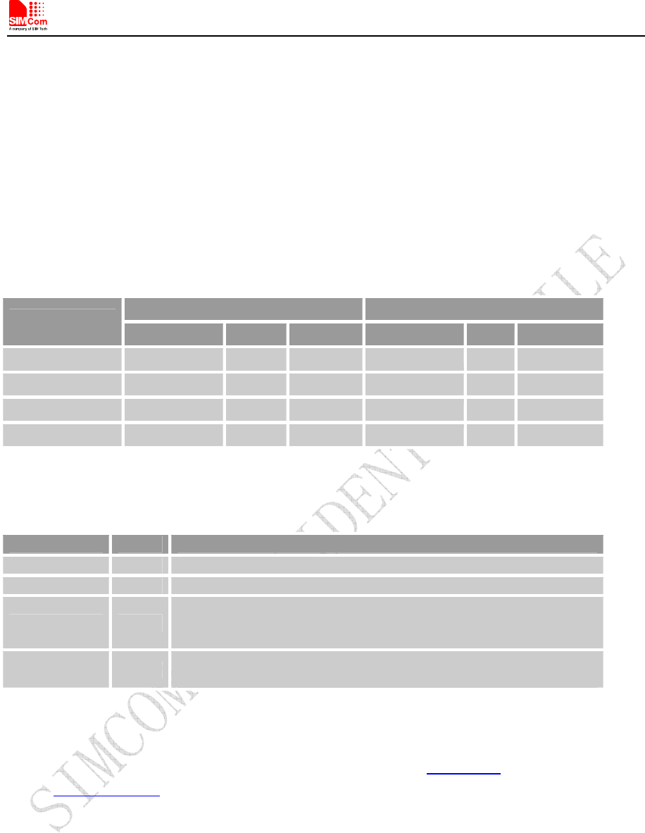
Table 17: Pin description
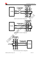
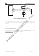
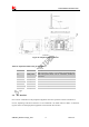
3.5.2 Application Guide
It is recommended to use an ESD protection component such as ST (www.st.com
) ESDA6V1W5 or ON
SEMI (www.onsemi.com
) SMF05C. Note that the SIM peripheral circuit should be close to the SIM card
socket. The reference circuit of the 8-pin SIM card holder is illustrated in the following figure.
3.0V mode 1.8V mode
Pin name
Min Typ Max Min Typ Max
V_USIM 2.7 3.00 3.3 1.65 1.8 2.0
USIM_RESET 0.8* V_USIM 3.00 V_USIM 0.8* V_USIM 1.8 V_USIM
USIM_CLK 0.7* V_USIM 3.00 V_USIM 0.8* V_USIM 1.8 V_USIM
USIM_DATA 0.7* V_USIM 3.00 V_USIM 0.8* V_USIM 1.8 V_USIM
Pin name Pin Description
USIM_CLK 19 USIM Card Clock
USIM_RESET 18 USIM Card Reset
USIM_DATA 17
USIM Card data I/O, which has been pulled up with a 22kR resistor to
V_USIM in module. Do not pull up or pull down in users’ application
circuit.
V_USIM 20
USIM Card Power output depends automatically on USIM mode,one
is 3.0V±10%, another is 1.8V±10%. Current is less than 50mA.