
User's Manual

Smart Machine Smart Decision
SIM5320A_Hardware Design_V1.01 2011-2-29
33
3.4.1 Pin Description
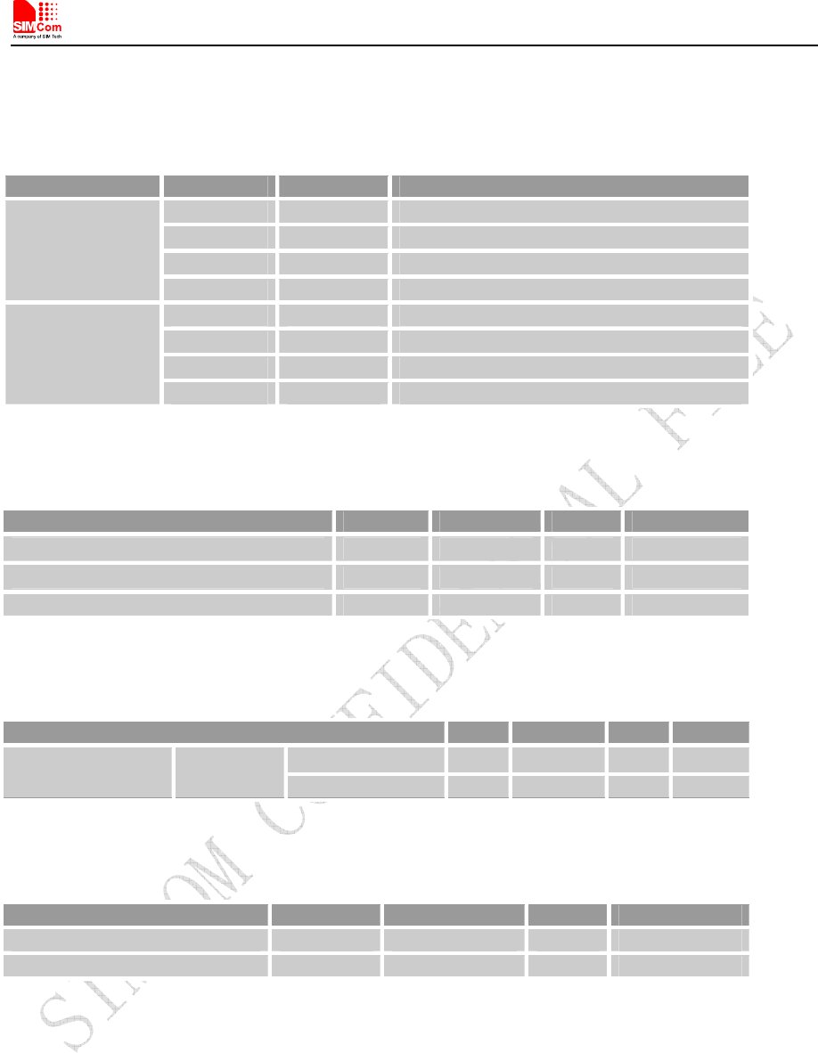
Table 11: Pin description
Audio channel Pin name Pin No. Function
MIC1P 23 MIC positive input
MIC1N 24 MIC negative input
EAR1P 26 Receiver positive output
Normal
EAR1N 25 Receiver negative output
MIC1P 23 MIC positive input
MIC1N 24 MIC negative input
SPK_P 22 Loudspeaker positive output
Hand-free
SPK_N 21 Loudspeaker negative output
Table 12: MIC input characteristics
Parameter Min Typ Max Unit
Working Voltage - 1.8 - V
Working Current 0.07 0.4 1 mA
External Microphone Load Resistance 1.2 2.2 k Ohms
Table 13: Audio output characteristics
Parameter Min Typ Max Unit
Load resistance 27 32 - Ohm Normal
(EAR_P,EAR_N)
Differential
Output power - 50 - mW
Table 14: Speaker output characteristics
Parameter Min Typ Max Unit
Quiescent Current - 2.5 4 mA
Output power(1KHz) - 500 - mW
3.4.2 Design Guide
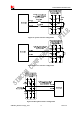
There are three audio channels in SIM5320A,including speaker output , receiver output and microphone
input.
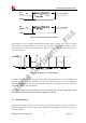
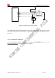
SPEAKER circuit in SIM5320A is a Class-D amplifier, optional EMI filter is shown in the following
figure; these components (two ferrite beads and two capacitors) can reduce electromagnetic interference. If
used, they should be located beside SPK_P and SPK_N pins. Considerable current flows in the channels,
so wider PCB traces are recommended (~ 20 mils).