
User's Manual

Smart Machine Smart Decision
SIM5320A_Hardware Design_V1.01 2011-2-29
31
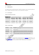
3.3.1 Pin Description
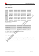
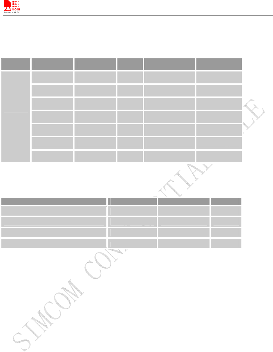
Table 9: Pin description
Pin type Pin name Pin No. I/O Active voltage Default Status
UART_RXD 68 I H Pull-Down
UART_TXD 71 O H Pull-Up
UART_RTS 66 O H
UART_CTS 67 I H Pull-Up
UART_DTR 72 I H Pull-Up
UART_DCD 70 O H
UART
UART_RI 69 O H
More pin information refers to chapter 2.2.
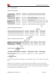
Table 10: Logic level
Parameter Min Max Unit
Logic low input 0 0.3*VDD_EXT V
Logic high input 0.7 *VDD_EXT VDD_EXT +0.3 V
Logic low output GND 0.2 V
Logic high output VDD_EXT -0.2 VDD_EXT V
Note: VDD_EXT (=2.6V) is e reference voltage in module internal interface.
All pins of all serial ports have 8mA driver capacity.
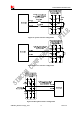
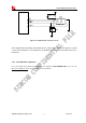
3.3.2 Application Guide
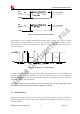
If UART port is used in Null Modem, the pin “RI” can be used as an interrupt signal to HOST. Normally it
will keep high logic level until certain condition such as receiving SMS, voice call (CSD, video) or URC
reporting, then “RI” will change to low logic level to inform the master (client PC). It will stay low until
the master clears the interrupt event with AT command.