
User's Manual
Smart Machine Smart Decision
SIM5320A_Hardware Design_V1.01 2011-2-29
25
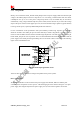
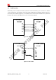
Make sure that the NTC thermistor can meet the above requirement. User can also add some resistors to
get desired voltage. The value of R1, R2 can be calculated according to the NTC curve and the above table.
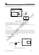
Please refer to the following circuit for user’s application.
Figure 12: Application circuit
Normally R1=750Ω. Then the input voltage can be calculated by the following formula:
Vadc=2.2* Rf/(Rf+9.76+0.75 )(V) —— Rf= Rt*R2/(Rt+R2)
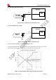
User can take out R2 value through the existing Vadc and the value of NTC thermistor in a specific
temperature.
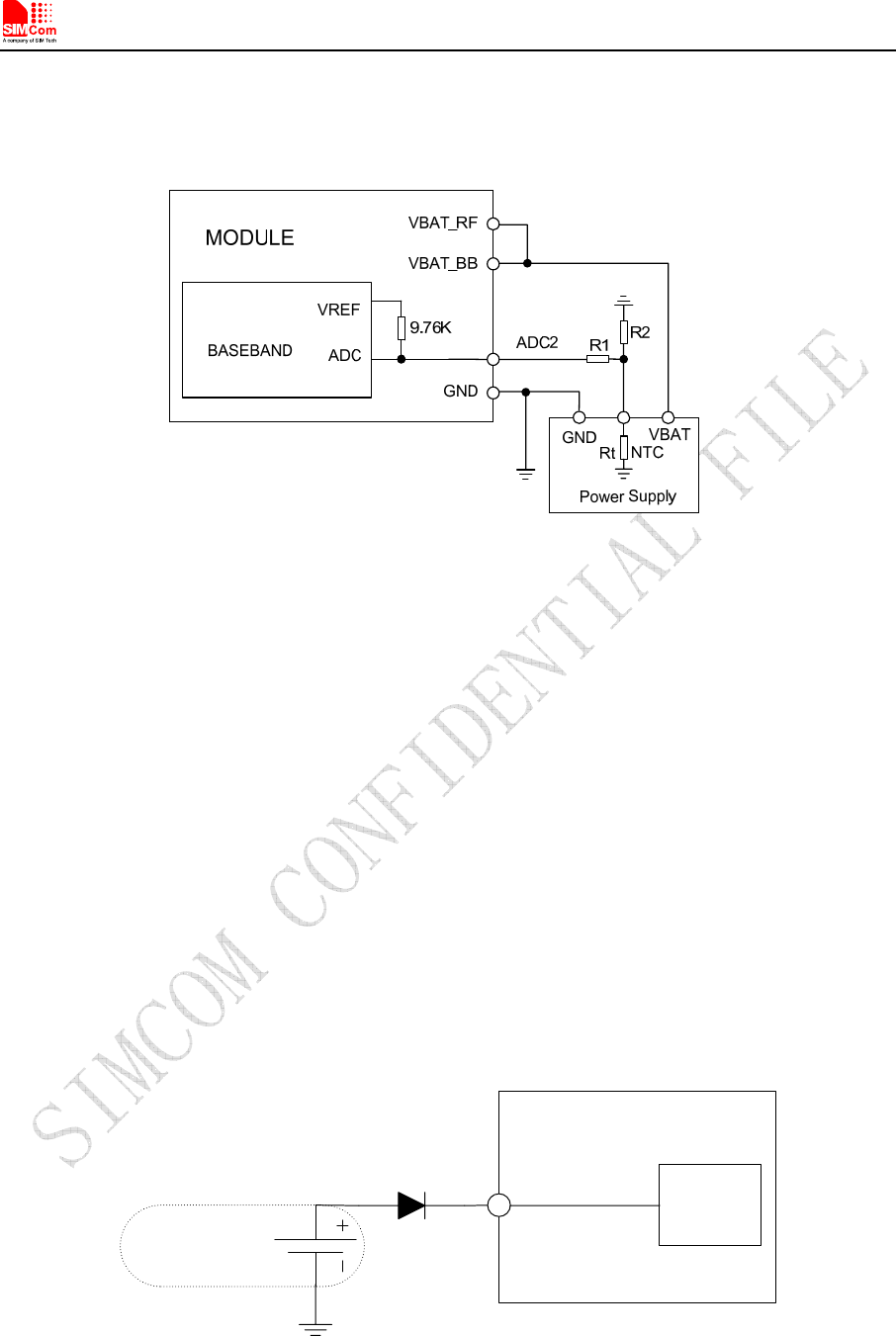
3.1.3 RTC Backup
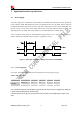
The module uses RTC (Real Time Clock) to update and maintain inherent time and keeps system alive at
no power supply status. The RTC power supply of module can be provided by an external capacitor or a
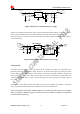
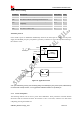
battery (non-chargeable or rechargeable) through the VRTC. The following figures show various reference
circuits for RTC back up. The discharge current is less than 10uA. If this feature is used, please refer to the
AT commands “AT+CTZU” and “AT +CTZR”.
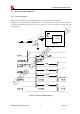
z External capacitor backup
RTC
Core
MODULE
VRTC
Non-chargeable
Backup Battery
Figure 13: RTC supply from capacitor