
User's Manual
Smart Machine Smart Decision
SIM5320A_Hardware Design_V1.01 2011-2-29
21
3 Application Interface Specification
3.1 Power Supply
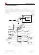
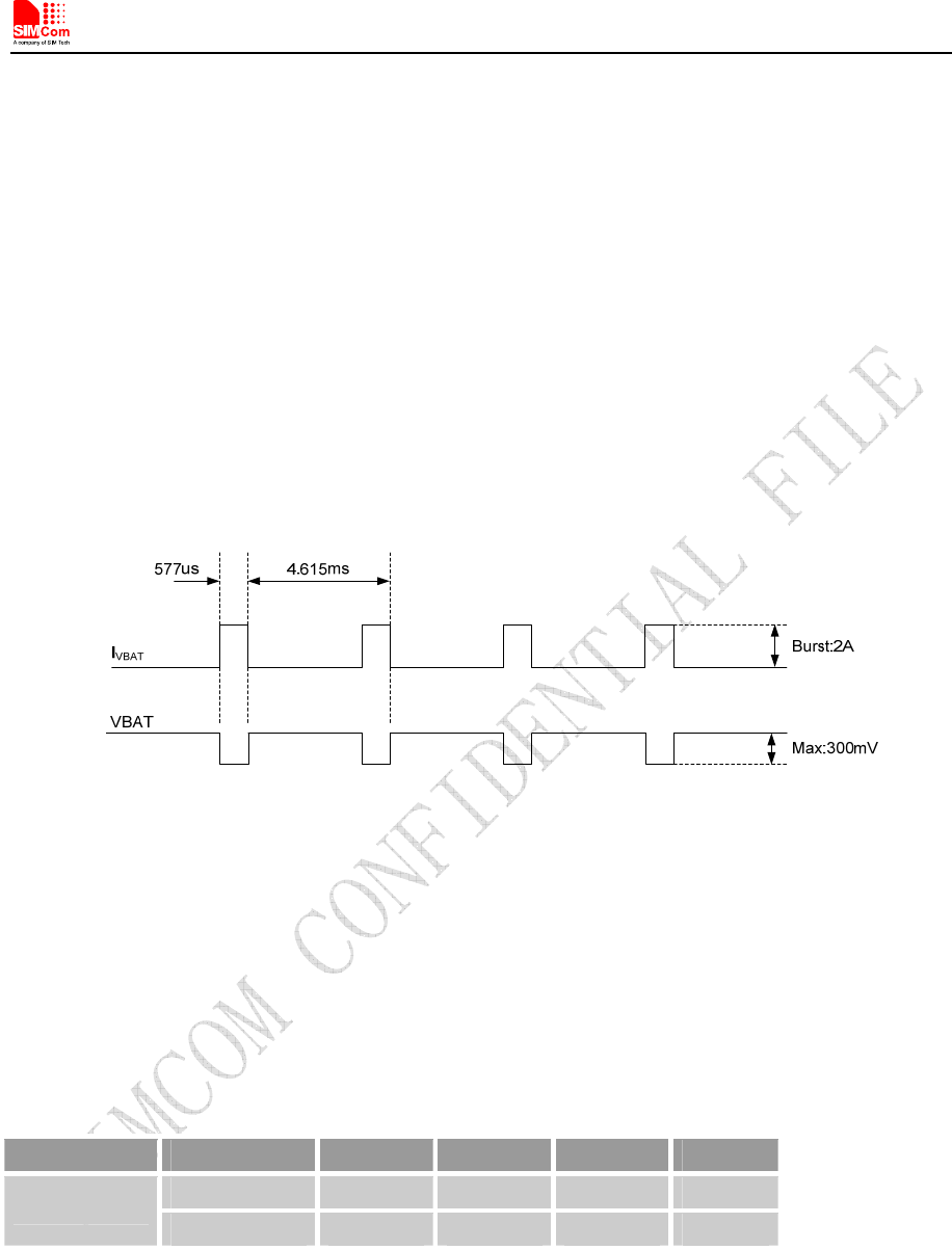
The power supply pins of SIM5320A include VBAT_RF and VBAT_BB. VBAT_RF directly supplies the
power to RF PA; VBAT_BB supplies the power to the baseband system. For the VBAT_RF, the ripple due
to GSM/GPRS emission burst (every 4.615ms)may cause voltage drop, and the current consumption rises
typically to peak of 2A. So the power supply must be able to provide sufficient current up to 2A. The
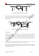
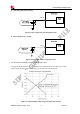
following figure is the VBAT_RF voltage ripple wave at the maximum power transmit phase.
The test condition: VBAT_RF=4.0V, VBAT maximum output current =2A, C
A
=100 µF tantalum capacitor
(ESR=0.7Ω) and C
B
=1µF(Please refer to Figure 8—Application circuit).
Figure 7: VBAT_RF voltage drop during burst emission (GSM/GPRS)
3.1.1 Power Supply Pin
Two VBAT_RF and two VBAT_BB pins are dedicated to connect the supply voltage.
Table 5: Pin description
Pin type Pin name Min Typ Max Unit
VBAT_RF 3.3 3.8 4.2 V
POWER
VBAT_BB 3.3 3.8 4.2 V
Note: 1.Though the VBAT_RF and VBAT_BB are supplied by the same voltage level, they are different pins. VBAT_RF
is for RF section and VBAT_BB is for baseband system.
2. When the module is power off, users must pay attention to the issue about current leakage. Refer to Chapter 3.10.2
Note2.