
Installation Instructions

SIM5216A _HD_V1.02 Hardware Design
SIM5216A _HD_V1.02 26.08.2010
48
SD_DATA3 SD_DATA3 NC
SD_CLK SD_CLK MMC_CLK
SD_CMD SD_CMD MMC_CMD
VREG_AUX SD_VDD MMC_VDD
Note
:
SD card interface function is supported by SIM5216A software. You can use
VREG_AUX for power supply of SD card and as the pull up power for data lines.
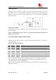
3.18 PCM Interface
SIM5216A provides hardware PCM interface for external codec. PCM interface pins are
multiplex on GPIOs(default setting). Use AT+CPCM command to change pins function between
PCM function and GPIOs.If enbale PCM function ,AT+CPCM command can be used to configure
the PCM mode user want. Also the slot of PCM can be configured by AT+CPCMSLOT.
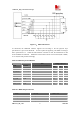
SIM5216A PCM interface can be used in two modes:
1) the default mode is its auxiliary PCM (8 kHz long sync mode at 128kHz clk);
2) the other mode is its primary PCM (8 kHz short sync mode at 2048 kHz clk).
In short-sync (primary PCM) mode, the SIM5216A can be a master or a slave. In long-sync
(auxiliary PCM) mode, the SIM5216A is always a master; there is no slave support.
SIM5216A support 3 PCM formats: 8 bits (
υ-law or A-law) and 16 bits (linear).
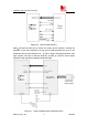
The PCM interface is a 4 pin, digital interface that enables PCM communication between the
Module and an external codec or DSP. Both the PCM interface modes, auxiliary and primary, use
the same SIM5216A pins. The PCM pin assignment is shown in the table below.
Note: Please reference document [22] for detailed information of PCM Application Note.
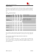
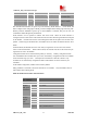
Table 27 : PCM pin assignment
Pins Pin
No.
AUX_PCM
functionality
Primary_PCM
functionality
Description
PCM_CLK/GPIO3 31 AUX_PCM_CLK PCM_CLK PCM clock for PCM
communication to
external codec
PCM_SYNC/GPIO2 30 AUX_PCM_SYNC PCM_SYNC PCM data strobe for
PCM
communication to
PCM
mode
SYNC CLK
MODE Format Slot
Auxiliary 8KHz 128KHz Master Only slot 0
Primary 8KHz 2.048MHz Slave/Master
A-law(8 bits)
υ-law(8bits)
linear(16 bits)
0~15(Changed by
AT command:
at+cpcmslot)
Default:slot 0