
Installation Instructions

SIM5216A _HD_V1.02 Hardware Design
SIM5216A _HD_V1.02 26.08.2010
41
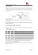
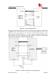
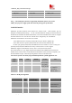
Figure 23: status LED circuit
Notes: 300R Resistor’s value depends on LED.
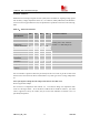
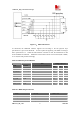
And status indicating table is as follow.
Table 21:meanings of status LED
Status Data Voice
Always On Searching Network Searching Network/Call Connect
200ms ON, 200ms OFF Data Transmit
800ms ON, 800ms OFF Registered network Registered Network
Off Power Off
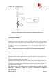
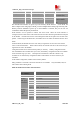
GPIO4 can be used to control RF close or on, the Flight Mode Switch logic table is shown
below. You can
use AT Command to read or to write GPIO2, GPIO3, GPIO5 status (High or Low
level).
Table 22:Logic of GPIO4
Use AT Command to read or write GPIO2, GPIO3, GPIO5 status (High or Low level).
NOTE
:
For SIM5216A, GPIO0, GPIO2, GPIO3 and GPIO5 can be multiplex function, you
can use them as PCM interface to connect extend codec. Please refer section 3.18 and
document [1] for detail information.
GPIO4 Status Module Action
L Flight Mode: RF is closed.
H Normal Mode: RF is working.