
Installation Instructions

SIM5216A _HD_V1.02 Hardware Design
SIM5216A _HD_V1.02 26.08.2010
40
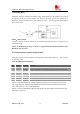
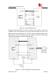
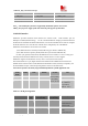
3.12 Module Reset
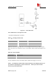
SIM5216A also have a RESET pin (PIN29) input, When should reset the module, one can push
the RESET pin to low and the module reset. Because the Reset pin has been pulled up in
SIM5216A, there is no need to pull it up in application circuit. The internal circuit about RESET
pin is shown below.
NOTE
:
50ms<t<200ms.
In order to improve the ESD of Reset pin, the bidirectional ESD component is suggested to be
used on Reset pin.
NOTE: In automatically powering on mode, it is suggested that the SIM5216A should reset by
RESET pin after power on.
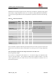
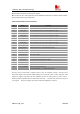
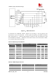
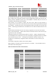
3.13 General purpose input & output (GPIO)
SIM5216A provides a limited number of General Purpose Input/Output signal pin. Please check
the following table:
Table 20: GPIO Pins of SIM5216A
GPIO0 is used for interrupt pin, default triggering mechanism is level trigger, and low level
will trigger interrupt. After interrupt, SIM5216A would send out Alarm information to host
CPU. Please Refer to “AT Command Manual”.
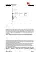
GPIO1 is used to control Status LED, the LED driving circuit of GPIO1 is shown below, and
status table is Table 23.
Pin Name Direction Function
65 GPIO0 Input,
interrupt
Input Port with interrupt/PCM_DIN
Use AT Command to set interrupt triggering mechanism & polarity .
10 GPIO1 Output used as status LED driver
30 GPIO2 Input General Purpose Input Port without interrupt/PCM_SYNC
31 GPIO3 Output General Purpose Output Port (default value: Low Level)/PCM_CLK
32 GPIO4 Input
RF Control Interrupt:Flight Mode Switch
33 GPIO5 Output General Purpose Output Port (default value: Low Level)/PCM_DOUT