
Installation Instructions

SIM5216A _HD_V1.02 Hardware Design
SIM5216A _HD_V1.02 26.08.2010
37
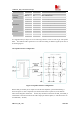
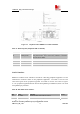
Table 16: Signal of USIM interface (board-to-board connector)
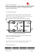
Following is the reference circuit of the USIM interface. We recommend using an Electro-Static
discharge device ST (
www.st.com ) ESDA6V1W5 or ON SEMI (www.onsemi.com ) SMF05C
for “ESD ANTI”. If you remove ESD components, please replace them with 33pF and 10pF
capacitors, it’s good for EMI performance. Note that the USIM peripheral circuit close to the
USIM card socket.
You can select the 6 pins USIM card. The reference circuit about 6 pins USIM card illustrates as
in the following figure.
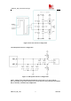
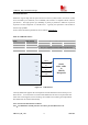
Figure 20: USIM interface reference circuit with 6 pins USIM card
*Note:
USIM_DATA has been pulled up with a 22kR resistor to V_USIM in module. So
please do not pull up or pull down in your application circuit. As shown in above figure,
SMF05C is used for ESD protection for SIM interface. And 220nF capacitor on V_USIM is
used to reduce interference
3.9.2 Design considerations for USIM card holder
For 6 pins USIM card, we recommend to use Amphenol C707 10M006 512 2. You can visit
http://www.amphenol.com
for more information about the holder.
Pin Signal Description
57 V_USIM
USIM Card Power output depends automatically on USIM mode,
one is 3.0V±10%, another is 1.8V±10%. Current is about 10mA.
56 USIM_DATA USIM Card data I/O, which has been pulled up with a 22kR
resistor to V_USIM in module. So please do not pull up or pull
down in your application circuit.
12 USIM_CLK USIM Card Clock
13 USIM_RESET USIM Card Reset