
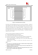
Installation Instructions

SIM5216A _HD_V1.02 Hardware Design
SIM5216A _HD_V1.02 26.08.2010
24
3.5.4 Wake up SIM5216A from Sleep Mode
When SIM5216A is in SLEEP mode, the following method can wake up the module.
z USB interface active
z Receive a voice or data call from network to wake up SIM5216A.
z Receive a SMS from network to wake up SIM5216A.
z Receive a interrupt signal from GPIO0
z GPIO4 state change.
z Receive AT command from UART.
z UART DTR signal changed.
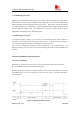
Normally DTR pin will stay high but in certain condition when serial port is used in Null
Modem(3-line mode). When host wants to wake up SIM5216A, it can pull down DTR for about
12ms(since SIM5216A has a debounce time of 10ms for mistaken interrupt checking). Then DTR
will trigger an interrupt which will finally cause SIM5216A to be waken up from sleep mode.
Note: One can enable/disable such function by AT+CDTRISRS, also One can configure the
DTR’s trigger condition by AT+CDTRISRMD(only level trigger condition has debounce time).
Currently the function is enabled by default and the trigger condition is low level. Please
reference document [23] for detailed information of Waking_up_Application_Note.
WARNING!!!: when DTR has been pulled down/up long enough to trigger the interrupt one
must recover DTR to original status or the interrupt will be triggered all the time and SIM5216A
may crash.
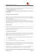
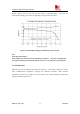
3.6 RTC backup
The RTC (Real Time Clock) power supply of module can be provided by an external battery or a
battery (rechargeable or non-chargeable) through the VRTC (PIN11) on the board-to-board
connector. You need only a coin-cell battery or a super-cap to VRTC to backup power supply for
RTC. The discharge current is smaller than 10uA. The module could update local time based
on universal time and time zone from network. (This feature must be supported by the network).
If this feature is used, please refer to AT command AT+CTZU and AT +CTZR.
Note: The VRTC default state can be designed to a NC pin in your circuit. If you need to use
the VRTC, You may connect the VRTC pin to a battery or a capacitor.
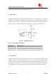
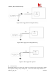
The following figures show various sample circuits for RTC backup.