
Installation Instructions

SIM5216A _HD_V1.02 Hardware Design
SIM5216A _HD_V1.02 26.08.2010
19
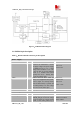
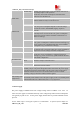
ESR) is recommended when one uses a Li battery. When you use a DC supply the Capacitor
must be a larger one (for example 2200u/10V), Multi-layer ceramic chip (MLCC) capacitors can
provide the best combination of low ESR and small size but may not be cost effective. A lower
cost choice may be a 100 µF tantalum capacitor (low ESR) with a small (0.1 µF to 1µF) ceramic
in parallel, which is illustrated as following figure. And the capacitors should put as closer as
possible to the SIM5216A VBAT pins. The following figure is the recommended circuit.
Figure 3:VBAT input
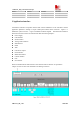
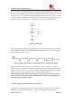
The following figure is the VBAT voltage ripple wave at the maximum power transmit phase,
the test condition is VBAT=4.0V, VBAT maximum output current =2A, C
A
=100 µF tantalum
capacitor (ESR=0.7Ω) and C
B
=1µF.
Figure
4:VBAT voltage drop at the maximum power transmit phase (GSM)
And make sure that the capacitor is close to VBAT pins of 70 pins connector. If a DC/DC or
LDO is used for power supply of the module, you should make sure that the peak current of power
supply can rise up to 2A (4.0V). The reference design is putting one big capacitor at the output
of the DC/DC or LDO, and another big capacitor beside the 70 pins connector.
Note: If a DC/DC or LDO is used as power supply, besides a big capacitor close to the 70-pin
connector, another big capacitor (typically a 100 µF tantalum capacitor) is suggested to be put
at the output pin of the DC/DC or LDO.
3.3.1 Power supply pins on the board-to-board connector
Six VBAT pins of the board-to-board connector are dedicated to connect the supply voltage; six
GND pins are recommended for grounding. VRTC pin can be used to back up the RTC.