
Installation Instructions
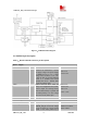

SIM5216A _HD_V1.02 Hardware Design
SIM5216A _HD_V1.02 26.08.2010
17
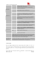
USIM_RESET O SIM Reset
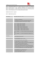
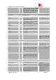
IIC interface
PIN NAME I/O DESCRIPTION DC CHARACTERISTICS
IIC_SDA I/O I2C data, if not in use, left open. It
has been pulled up with a 2.2kR
resistor to 2.6V in module. So there is
no need to pull up it in your
application circuit.
IIC_SCL O I2C clock output, if not in use, left
open. It has been pulled up with a
2.2kR resistor to 2.6V in module. So
there is no need to pull up it in your
application circuit.
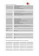
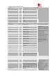
Other interface
PIN NAME I/O DESCRIPTION DC CHARACTERISTICS
Reset I System reset in, active low. Reset pin has been pulled
up in SIM5216A. Detail
description refer to chapter
3.12.
GPIO0/PCM_DIN I General Input PIN with interrupt. If
not in use, left open. It also can be
multiplexed as the PCM_DIN pin.
GPIO1 O Status Indicating LED Control.
GPIO2/PCM_SYNC I General Input PIN. If not in use, left
open. It also can be multiplexed as
the PCM_SYNC pin.
GPIO3/PCM_CLK O General Output PIN. If not in use, left
open. It also can be multiplexed as
the PCM_CLK pin.
GPIO4 I RF Control: Flight Modem switch
GPIO5/PCM_DOUT O General Output PIN. If not in use, left
open. It also can be multiplexed as
the PCM
_
DOUT
p
in.
VIHmin=0.7*VDD_EXT
*
VIHmax= VDD_EXT+0.3
VOLmin=GND
VOLmax=0.2V
VOHmin= VDD_EXT-0.2
VOHmax= VDD_EXT
*Note: module internal reference supply power: VDD_Ext=2.6V
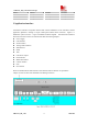
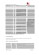
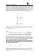
3.2 Operating modes
The following table summarizes the various operating modes, each operating modes will be
referred to in the following chapters.
Table 6:Overview of operating modes
Mode Function
Normal operation
Module Power
Off mode
Module will go to Power off mode when the Power on pin has
been pushed low for 2 Seconds.