
Installation Instructions

SIM5216A _HD_V1.02 Hardware Design
SIM5216A _HD_V1.02 26.08.2010
16
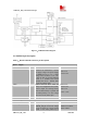
UART_TXD O Transmit Data, if not in use, left open.
UART_RTS O Request to Send, if not in use, left
open.
UART_CTS I Clear to Send, if not in use, left open.
UART_RI O Ring Indicator, if not in use, left
open.
UART_DCD O Data Carrier detection, if not in use,
left open.
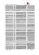
Camera interface
PIN NAME I/O DESCRIPTION DC CHARACTERISTICS
CAM_D2 I Bit 2 of RGB or YUV D0 video
component input
CAM_D3 I Bit 3 of RGB or YUV D1 video
component input
CAM_D4 I Bit 4 of RGB or YUV D2 video
component input
CAM_D5 I Bit 5 of RGB or YUV D3 video
component input
CAM_D6 I Bit 6 of RGB or YUV D4 video
component input
CAM_D7 I Bit 7 of RGB or YUV D5 video
component input
CAM_D8 I Bit 8 of RGB or YUV D6 video
component input
CAM_D9 I Bit 9 of RGB or YUV D7 video
component input
CAM_HSYNC I Video horizontal line synchronization
signal input
CAM_VSYNC I Vertical sync input
CAM_CLK O master clock output
CAM_PCLK I Pixel clock input
CAM_RESET O Master reset out, active low
CAM_STANDBY O
Power-down mode selection
“0”=Normal mode, “1”=Power-down
mode
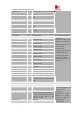
VILmin=0V
VILmax=0.3*VDD_EXT
*
VIHmin=0.7*VDD_EXT
VIHmax=VDD_EXT+0.3
VOLmin=GND
VOLmax=0.2V
VOHmin=VDD_EXT-0.2
VOHmax=VDD_EXT
All camera pins can be
configured as GPIOs.
Detail description refer to
chapter 3.16.
USIM interface
PIN NAME I/O DESCRIPTION DC CHARACTERISTICS
V_USIM O Voltage Supply for SIM card The voltage can be
selected by software to be
either 1.8V or 3V
USIM_DATA I/O SIM Data Output/Input, which has
been pulled up with a 22kR resistor to
V_USIM in module. So please do not
pull up or pull down in your
application circuit.
USIM_CLK O SIM Clock
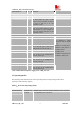
VILmin=0V
VILmax=0.3*V_USIM
VIHmin=0.7* V_USIM
VIHmax=V_USIM +0.3
VOLmin=GND
VOLmax=0.2V