
Installation Instructions

SIM5216A _HD_V1.02 Hardware Design
SIM5216A _HD_V1.02 26.08.2010
15
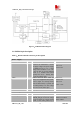
VBAT in module. The user should
keep it to low level for at least 64mS
when power on or power off the
system because the system needs
margin time to assert the software.
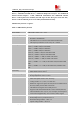
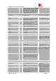
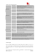
Audio interfaces
PIN NAME I/O DESCRIPTION DC CHARACTERISTICS
MIC_P
MIC_N
I Positive and negative voice-band
input If not in use, connect to ground
through a 100N capacitor.
Audio DC Characteristics
refer to chapter 3.8.4
HP_MICP I Auxiliary positive voice-band input,
if not in use, connect to ground
through a 100N capacitor.
EAR_P
EAR_N
O Positive and negative voice-band
output, if not in use ,left open
HPR
HPL
O Auxiliary right channel and left
channel voice-band output, if not in
use, left open.
SPK_P
SPK_N
O Loud Speaker Output, if not in
use ,left open
HKADC I Analog Digital Converter Input
VREG_AUX O LDO power output This LDO default output
voltage is 2.85V, and
driver current is rated for
250mA.
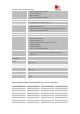
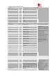
USB
PIN NAME I/O DESCRIPTION DC CHARACTERISTICS
USB_VBUS I USB power supply input, if not in
use, left open.
Vmax =5.25 V
Vmin =4.4 V
Vnor
m
= 5.0 V
USB_DP I/O Plus (+) line of the differential,
bi-directional USB signal to/from the
peripheral device. If not in use, left
open.
USB_DM I/O
Minus (-) line of the differential,
bi-directional USB signal to/from the
peripheral device. If not in use, left
open.
They are compliant with
the USB 2.0 specification.
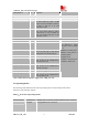
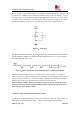
Serial interface
PIN NAME I/O DESCRIPTION DC CHARACTERISTICS
UART_DTR I Data Terminal Ready, if not in use,
left open.
UART_RXD I Receive Data, which has been pulled
down with a 15kR resistor to ground
in module, if not in use, left open. So
please don’t pull up or pull down in
y
our a
pp
lication circuit.
VILmin=0V
VILmax=0.3*VDD_EXT
*
VIHmin=0.7*VDD_EXT
VIHmax=VDD_EXT+0.3
VOLmin=GND
VOLmax=0.2V