
User's Manual


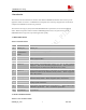

Table Of Contents
- Contents
- Version history
- 1 Introduction
- 2 SIM900B Overview
- 3 Application Interface
- 3.1 SIM900B Pin Description
- 3.2 Operating Modes
- 3.3 Power Supply
- 3.4 Power Up and Power Down Scenarios
- 3.5 Power Saving
- 3.6 Summary of State Transitions (except SLEEP mode)
- 3.7 RTC Backup
- 3.8 Serial Interfaces
- 3.9 Audio Interfaces
- 3.10 Buzzer
- 3.11 SIM Card Interface
- 3.12 LCD Display Interface
- 3.13 Keypad Interface
- 3.14 ADC
- 3.15 Behaviors of the RI
- 3.16 Network Status Indication
- 3.17 General Purpose Input Output (GPIO)
- 4 Antenna Interface
- 5 Electrical, Reliability and Radio Characteristics
- 6 Mechanics

SIM900 Hardware Design
Version history
Date Version Description of change Author
2010-04-08 1.01 Origin Huangqiuju
2010-05-31 1.02 Modify voltage domain , current consumption and
figure37
Huangqiuju
2010-06-23 1.03 §2.1, §3.3. §3.4 Modify the power supply range from
3.2V~4.8V to 3.1V~4.8V
§3.7, Modify the VRTC pin connection when RTC
backup is not needed.
Huangqiuju
SIM900_HD_V1.03 7 24.06.2010