
User's Manual
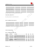
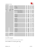
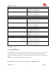

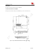


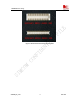
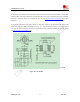
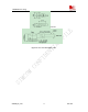
Table Of Contents
- Contents
- Version history
- 1 Introduction
- 2 SIM900B Overview
- 3 Application Interface
- 3.1 SIM900B Pin Description
- 3.2 Operating Modes
- 3.3 Power Supply
- 3.4 Power Up and Power Down Scenarios
- 3.5 Power Saving
- 3.6 Summary of State Transitions (except SLEEP mode)
- 3.7 RTC Backup
- 3.8 Serial Interfaces
- 3.9 Audio Interfaces
- 3.10 Buzzer
- 3.11 SIM Card Interface
- 3.12 LCD Display Interface
- 3.13 Keypad Interface
- 3.14 ADC
- 3.15 Behaviors of the RI
- 3.16 Network Status Indication
- 3.17 General Purpose Input Output (GPIO)
- 4 Antenna Interface
- 5 Electrical, Reliability and Radio Characteristics
- 6 Mechanics

SIM900B Hardware Design
6.5 RF connector
The RF connector in module side is a ultra small surface mount coaxial connectors (Part Number: U.FL-R-SMT,
vended by HRS). It has high performance with wide frequency range, surface mountable and reflows solderable.
Following is parameter (Figure 36). Certainly the user can visit http://www.hirose-connectors.com/
for more
information.
To get good RF performance in customer’s design, we suggest the customer to use the matching RF adapter cable
which is also supplied by HRS (Part Number: U.FL-LP(V)-040), the following figure 41 is the dimensions of
U.FL series RF adapter cable. The customer can get it from the cable’s manufacturer HRS, and for details, please
visit http://www.hirose-connectors.com/
.
Unit:mm
Figure 38: U.FL-R-SMT
SIM900B_HD_V1.03 24.06.2010
59