
User's Manual
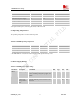
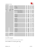


Table Of Contents
- Contents
- Version history
- 1 Introduction
- 2 SIM900B Overview
- 3 Application Interface
- 3.1 SIM900B Pin Description
- 3.2 Operating Modes
- 3.3 Power Supply
- 3.4 Power Up and Power Down Scenarios
- 3.5 Power Saving
- 3.6 Summary of State Transitions (except SLEEP mode)
- 3.7 RTC Backup
- 3.8 Serial Interfaces
- 3.9 Audio Interfaces
- 3.10 Buzzer
- 3.11 SIM Card Interface
- 3.12 LCD Display Interface
- 3.13 Keypad Interface
- 3.14 ADC
- 3.15 Behaviors of the RI
- 3.16 Network Status Indication
- 3.17 General Purpose Input Output (GPIO)
- 4 Antenna Interface
- 5 Electrical, Reliability and Radio Characteristics
- 6 Mechanics

SIM900B Hardware Design
Voice Call
GSM 850/EGSM 900 @power level #5 <300mA,Typical 250mA
@power level #12,Typical 110mA
@power level #19,Typical 80mA
DCS 1800/PCS 1900 @power level #0 <200mA,Typical 180mA
@power level #7,Typical 94mA
@power level #15,Typical 76mA
GPRS Data
DATA mode, GPRS ( 1 Rx,1 Tx ) CLASS 8
GSM 850/EGSM 900 @power level #5 <300mA,Typical 235mA
@power level #12,Typical 102mA
@power leve#19,Typical 74mA
DCS 1800/PCS 1900 @power level #0 <200mA,Typical 170mA
@power level #7,Typical 90mA
@power level #15,Typical 70mA
DATA mode, GPRS ( 3 Rx, 2 Tx ) CLASS 10
GSM 850/EGSM 900 @power level #5<450mA,Typical 440mA
@power level #12,Typical 185mA
@power level #19,Typical 125mA
DCS 1800/PCS 1900 @power level #0 <350mA,Typical 320mA
@power level #7,Typical 155mA
@power level #15,Typical 120mA
DATA mode, GPRS ( 4 Rx,1 Tx ) CLASS 8
GSM 850/EGSM 900 @power level #5 <300mA,Typical 273mA
@power level #12,Typical 145mA
@power level #19,Typical 120mA
DCS 1800/PCS 1900 @power level #0<300mA,Typical 205mA
@power level #7,Typical 130mA
@power level #15,Typical 110mA
Class 10 is default set when the module works at data translation mode, the module can also work at class 8 set by
AT command.
5.5 Electro-Static Discharge
The GSM engine is not protected against Electrostatic Discharge (ESD) in general. Therefore, it is subject to ESD
handing precautions that typically apply to ESD sensitive components. Proper ESD handing and packaging
procedures must be applied throughout the processing, handing and operation of any application using a SIM900B
module.
The measured values of SIM900B are shown as the following table:
Table 29: The ESD endure statue measured table (Temperature: 25 , Humidity:45% )℃
SIM900B_HD_V1.03 24.06.2010
53