
User's Manual
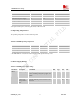
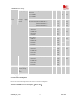


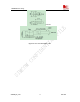
Table Of Contents
- Contents
- Version history
- 1 Introduction
- 2 SIM900B Overview
- 3 Application Interface
- 3.1 SIM900B Pin Description
- 3.2 Operating Modes
- 3.3 Power Supply
- 3.4 Power Up and Power Down Scenarios
- 3.5 Power Saving
- 3.6 Summary of State Transitions (except SLEEP mode)
- 3.7 RTC Backup
- 3.8 Serial Interfaces
- 3.9 Audio Interfaces
- 3.10 Buzzer
- 3.11 SIM Card Interface
- 3.12 LCD Display Interface
- 3.13 Keypad Interface
- 3.14 ADC
- 3.15 Behaviors of the RI
- 3.16 Network Status Indication
- 3.17 General Purpose Input Output (GPIO)
- 4 Antenna Interface
- 5 Electrical, Reliability and Radio Characteristics
- 6 Mechanics

SIM900B Hardware Design
Voltage ripple Normal condition, power control level for
Pout max
@ f<200kHz
@ f>200kHz
50
2
mV
POWER DOWN mode
SLEEP mode(BS-PA-MFRMS=2 )
(BS-PA-MFRMS=5 )
(BS-PA-MFRMS=9 )
50
1.5
1.2
1.0
uA
mA
mA
mA
IDLE mode
GSM 850
EGSM 900
DCS1800
PCS1900
22
22
22
22
mA
TALK mode
GSM 850
EGSM 900
DCS1800
PCS1900
235
247
181
170
mA
DATA mode, GPRS (3 Rx,2Tx)
GSM 850
EGSM 900
DCS1800
PCS1900
436
463
322
303
mA
I
VBAT
Average supply
current
DATA mode, GPRS (4 Rx,1Tx)
GSM 850
EGSM 900
DCS1800
PCS1900
270
282
215
205
mA
Peak supply
current (during
Tx
burst)
Power control level for Pout max. 2.0 A
5.4 Current Consumption
Please refer to the following table for the values of current consumption.
Table
28: SIM900B current consumption(VBAT=3.8V)
SIM900B_HD_V1.03 24.06.2010
52